
Fractography of Clinical Failures of Indirect Resin Composite Endocrown and Overlay Restorations
Abstract
Objectives. Compare failure modes and fracture origins using fractography on recovered clinically fractured parts of indirect resin composite endocrowns and overlay restorations on endodontically treated teeth (ETT). And more detailed information about indirect tooth resin composite restorations are accessible for you to learn on our website in Prosthodontics section.
Methods. Four endocrowns (3 molars, 1 premolar) and one overlay (molar) adhesively luted on ETT were recovered after fracturing during function. The time in service ranged between 4 and 48 months. The composite materials were (i) CAD/CAM LAVA Ultimate (N = 1), (ii) Premise Indirect (N = 2), and (iii) Colombus (N = 2). Fractography was performed by means of digital microscopy and SEM. Occlusal surfaces were checked for signs of fatigue degradation and contact wear. Cuspal plane angles were measured from profiles obtained from 3D digital microscope images with respectto the horizontal plane ofthe occlusal central crown groove.
Results. All five cases showed a wedge-opening mode I fracture, splitting the crown and tooth in two parts through the crown’s central groove. Classic brittle fracture features (arrest lines, twist and wake hackle) were easily identified on the fracture surfaces. Multiple origins were located along the central groove in conjunction with the presence of fatigue cracks. Contact wear surfaces showed pitting and cracking. Cuspal plane angles were around 30–35◦, except a 50◦ palatal cusp slope for the Lava Ultimate overlay.
Significance. Fractography on clinical fractures of resin composites was enlightening. Occlusal surface fatigue degradation from cyclic loading, mode I fracture from applied mastication forces on cuspal planes, and stress concentration within the crown’s central groove, indicate limitations of use of these materials for endocrowns in posterior teeth.
1. Introduction
Endocrowns and overlays have been proposed to restore endodontically treated teeth (ETT), relying on adhesive techniques as opposed to more invasive post and core build-ups for retention [1–3]. Both endocrowns and overlays (Fig.1) are full cusp coverage restorations of the missing crown surface. An overlay restores only the coronal part of the tooth, while the pulp chamber is fully filled by a directly stratified resin- composite material bonded to the dentin. An endocrown is a crown with a central extension inside the pulp chamber. Retentive undercuts of the pulp chamber may be removed by the preparation or previously filled with resin composite before adhesive luting of the restoration.
A systematic review [4], and two 10 to 12-year retrospective clinical evaluations [5,6] have been recently published supporting the use of endocrowns for rehabilitation of posterior ETT. Materials such as feldspar-based ceramic [6–8], polymer-infiltrated feldspar-based ceramic [5], lithium-(di)silicate glass-ceramics [5,9] as well as resin-composite materials [10], have been clinically used for endocrowns.
Recently, developments in particulate filled resin composites [11] have broadened their use for indirect restorations owing to improved strength, toughness and fatigue behavior while maintaining a modulus of elasticity similar to that of dentin [12–15]. Besides having acceptable mechanical properties, the main advantages cited for resin-composite restorations are ease of processing (indirect or CAD/CAM made), high polishability, as well as in-situ repairability in case of a clinical partial fracture [16,17].
The literature contains a wealth of in vitro testing information regarding these novel resin composites for indirect or CAD/CAM crown restorations, but clinical fracture events, although reported in survival data from longitudinal studies [5,18], are rarely fractographically documented and analyzed.
One exception is a recent paper by Lohbauer et al. [19] reporting on fractured implant-supported CAD/CAM resin-composite crown reconstructions. Fractures are well known adverse outcomes for resin-composites in Class I and II restorations and were reported to be the main reasons for failure, along with recurrent caries, in a systematic review and meta-analysis [20]. Therefore, when in-service failure of large adhesively luted resin-composite restorations, such as endocrowns, involve a fracture through the pulp chamber resulting in a loss of the tooth, the value of a careful failure analysis of the recovered crown-tooth parts in order to understand the circumstances around such a catastrophic event becomes readily apparent [21,22]. As already well explained and often implemented for ceramic restorations [22–25], failure analysis of recovered fractured parts using fractographic means, such as stereomicroscopy or digital optical microscopy with large depth-of-field combined with SEM, provides key information as to the fracture mode, fracture origin(s) and direction of crack propagation based on the recognition of fracture surface markings. The request for recovered polymer-based failed restorations for further analysis and attempts to correlate this information with in vitro test outcomes has been made by several authors [21,26–28]. Additional information regarding the circumstances of the fracture event, time in service, tooth location, crown design and processing method all aid in formulating plausible explanations for such unfa- vorable outcomes. For particulate reinforced resin composite restorations, evidence of damage in the form of abrasive wear or fatigue (micro)cracking should be investigated on the cyclic loaded occlusal surface, as these phenomena will greatly contribute to the overall reduction of the mechanical properties of the material [29,30].
This paper reports, for the first time in the dental literature, extensive fractographic failure analysis of recovered clinical fractured parts of resin composite endocrowns and overlay restorations adhesively luted on endodontically treated teeth. The failure analysis compares fracture modes, crack origins and locations, surface contact wear and fatigue degradation for three different resin-composite materials processed by either indirect layering technique or CAD/CAM. Findings are discussed and explained with respect to biomechanics and material science considerations relevant to resin composites.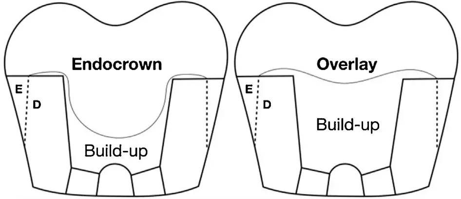 Fig. 1 – Endocrown and overlay restoration schematic with respect to pulp chamber build-up.
Table 1 – Recovered indirect composite resin restoration: brand, manufacturer, processing, composition, tooth location (FDI / universal numbering system, Uni) and months (mths) in service before fracture.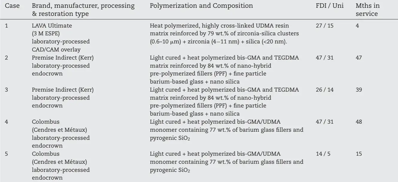
2. Materials and methods
2.1. Recovered fractured crown parts
Four endocrowns (3 molars, 1 premolar) and one overlay (molar) adhesively cemented on endodontically treated teeth which fractured during function were recovered by the treating dentists and donated to the University Clinics of Dental Medicine of the University of Geneva for failure analysis.
The recovered endocrowns were indirect (layered) resincomposites whereas the overlay was an indirect CAD/CAM processed restoration. The times in service before fracture ranged between 4 and 48 months. Table 1 summarizes the recovered restorations specifying brand name, manufacturer, composition, processing, tooth location (FDI / universal numbering systems) and months in service. When available, additional information such as intra-oral photograph of the in situ fractured restoration, adhesive luting procedure, as well as the circumstances of the fracture event as described by the patient were collected.
Fig. 2 shows in situ images of two indirect resin-composite restorations split in half through the anatomical central groove: Case 1 (Fig. 2a) is a CAD/CAM made overlay (LAVA Ultimate) which fractured after 4 months; Case 4 (Fig. 2b, c) is an indirect composite endocrown (Colombus) which fractured after 48 months.
In this particular case, a careful opening with an explorer (Fig. 2c) of the cracked endocrown restoration was needed for recovering of the looser lingual fragment.
Such documentation helps in identifying possible damage on the fractured surface from the explorer. All five fracture cases involved not only the restoration, but also the tooth-root structure ending, with a total loss of the tooth which had to be extracted. When both halves of the failed restoration were available, fractography was performed on each of them.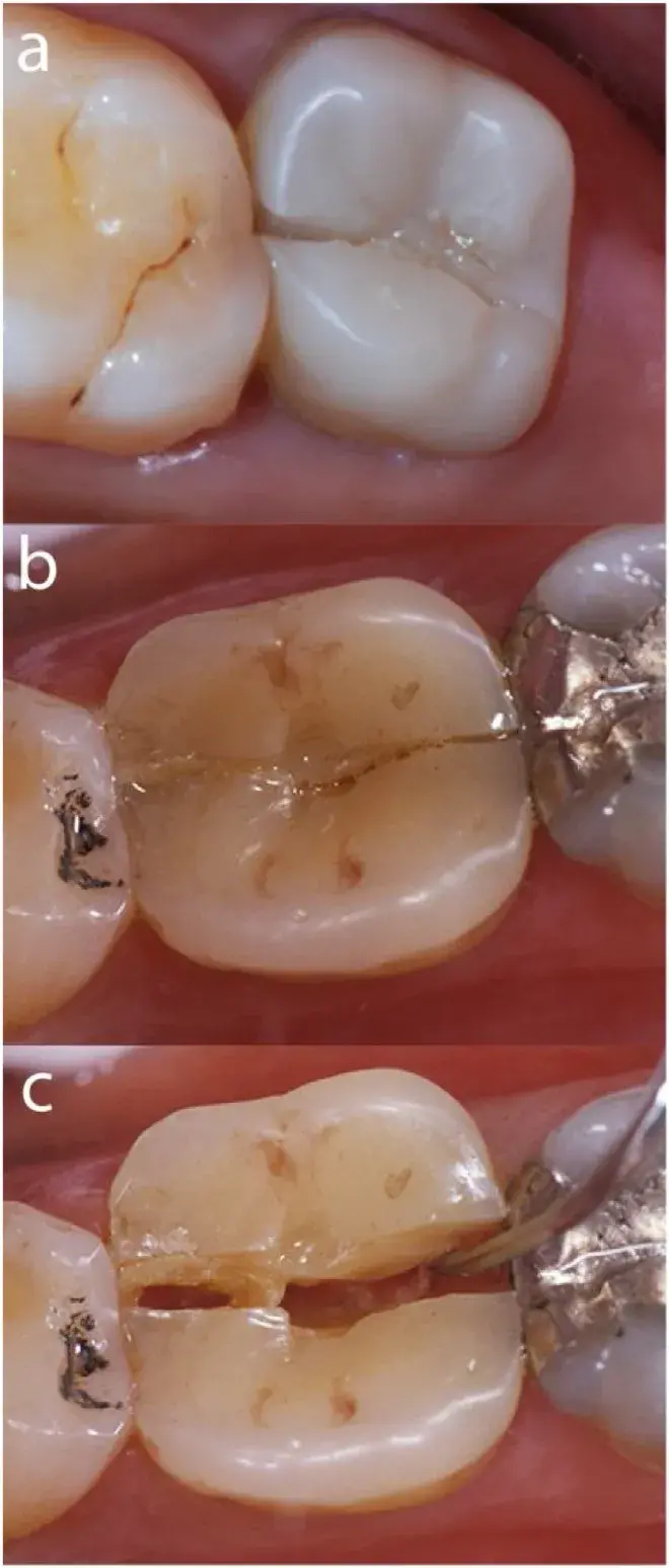 Fig. 2 – In situ clinical images of two indirect resin-composite restorations split through the central groove. Fig. 2a: CAD/CAM overlay (LAVA Ultimate) (Case 1); Fig. 2b: Indirect composite endocrown (Colombus) (Case 4).
In this particular case, a careful opening with an explorer (Fig. 2c) of the cracked restoration was needed for recovering of the looser lingual fragment. Such documentation is important as it helps in identifying possible damage from the explorer on the fractured surface.
2.2. Fractographic failure analysis
The recovered fractured parts (restoration with tooth) were first cleaned and disinfected in an ultrasonic bath for 3 min with 5% sodium hypochlorite, followed by 3 min in distilled water and finally one minute in pure ethanol. A stereomicroscope (Olympus SZX9) and a digital microscope with a large depth of field (Keyence VHX 5000) were used for the initial doc- umentation. The failure analysis included determining mode of failure, and identifying characteristic fracture markings (arrest lines, wake and twist hackle) on the fracture surface to aid in determining the origins offracture. In addition, evidence of occlusal surface contact wear and signs of fatigue cracking were recorded. Transillumination with an external quartz- tungsten-halogen light source was used to reveal the presence of such fatigue cracks adjacent to areas of occlusal contact wear and the fracture surface. A preliminary mapping of the observed features was then sketched out, indicating areas of interest for further high magnification analysis utilizing the SEM. After the optical microscope evaluations, the specimens were glued on stubs and gold coated (20−100 nm) for detailed SEM (Sigma 300 V P, Zeiss) evaluation of the fracture origins, characteristic surface crack features, and evidence of occlusal surface degradation such as wear, fatigue cracking and pitting.
3. Results
3.1. Fractographic failure analysis
Case 1: CAD/CAM (Lava Ultimate) resin-composite molar No. 27 / 15 overlay
The bonded overlay on tooth 27 had been made with a fully digital chair-side method, four months prior to the fracture event using a CAD/CAM resin-composite bloc (LU). The internal pulp chamber was built-up with a nano-hybrid resin-composite (T) (Tetric EvoCeram A3, Ivoclar Vivadent) and the restoration cemented with a photocuring hybrid resin-composite (Tetric, Ivoclar Vivadent) using an etch-and-rinse adhesive system (Optibond FL, Kerr Dental). Regarding the circumstance of the fracture, the patient reported biting on something hard during mastication.
Fig. 3 illustrates the fracture mode I (crack opening)through the occlusal central anatomical groove of the composite CAD/CAM restoration. Major occlusal contacts are marked with red arrows (and dots in the inset photo) as identified by stereomicroscopy. On the mesial proximal view, the red arrows indicate the approximate applied loading direction on the cuspal planes during chewing generating maximum stress levels within the central groove from which a wedge-opening fracture started. Fig. 4 shows a 3D digital microscopy occlusal view of the overlay in case 1 (Fig. 4a) with the fracture running through the central groove splitting the crown and tooth in two parts.
The red arrows point to the multiple fracture origins on the occlusal crown surface. The fracture surface (Fig. 4c) of the recovered buccal crown-tooth part shows multiple crack origins (red arrows) followed by numerous semicircular concentric arrest lines created at successive times as a result of multiple distinct loading events propagating the crack on different planes. The crack propagation directions (dcp) are indicated by black arrows and run apically towards the roots.
The Lava Ultimate (LU) overlay’s thickness is, in its thinnest part, 2.3 mm. Underneath the overlay restoration is a build-up layer of resin composite Tetric Ceram (Tetric) filling in part of the tooth pulp chamber. Transillumination (Fig. 4b) reveals occlusal surface fatigue cracks extending along the central mesio-distal groove. On the occlusal crown surface, a dominant oblong-shaped contact wear facet of 20 × 30 mm is visible on the disto-buccal cuspal plane (Fig. 4a–c,) as well as a smaller one on the mesio-buccal cusp plane (Fig. 4c). These wear surfaces will be further discussed in Figs. 5 and 6. Fig. 5 shows SEM photomicrographs of the buccal fractured part of the Lava Ultimate overlay. Red arrows indicate multiple fracture origins located within the central groove. Direction of crack propagation (dcp) moves apically. Higher magnifications of the fatigue cracks in the vicinity of origin No1 (white box) are
Lillustrated in Fig. 5b, c. Some of these cracks are penetrating deep (>1 mm) into the bulk (Fig. 5a). Concentric arrest lines (al) spaced out indicating that the crack progressed in stages, are visible in Fig. 5a. In between arrest lines are many fine twist hackle (th) which are hackle that have rotated from the original crack plane in response to a lateral rotation in the axis of principal tension. Zone 2 on the mesio-buccal cuspal plane and zone 3 on the disto-buccal cuspal plane are wear contacts with a pitted appearance as fillers from the composite material were removed by the wear process. Zone 1 (Fig. 5a, b) corresponds to the unpolished CAD/CAM machining marks.
Further analysis of the fracture origin No1 is shown in Fig. 6. Fatigue cracks are visible on the occlusal surface penetrating ∼200 m deep into the bulk of the composite overlay with evidence of some crack branching at 90◦. Multiple arrest lines (al) are showing the stop and go process of the advancing crack progressing apically. Multiple twist hackle (th) are present between each arrest line. Fig. 7 shows further details of the Lava Ultimate wear facet on the disto-buccal cuspal plane in Zone 3 (see also Fig. 4c and Fig. 5a). Such wear scars are an ongoing process of polymer matrix cracking and matrix-filler interface debonding (Fig. 7c,d) accelerating the localized loss of material and increasing the pitting of the surface. The porous web-like material in Fig. 7d may be either part of a residual resin layer and cohesive failure in the matrix or some sort of organic deposits which were not eliminated by the cleaning process of the specimen before adding a thin 20 nm gold-coating for the SEM analysis. Potential degradation/erosion of the resin matrix due to exposure to oral and bacterial enzymes cannot be excluded.
Case 2: indirect layered resin-composite molar No. 47 / 31 endocrown (Premise Indirect)
As with case 1, the fracture split the crown in two parts through its central mesio-distal occlusal groove in a crack opening mode I fracture after 47 months of intraoral function.
The recovered buccal part is viewed under a stereomicro- scope (Fig. 8a, b) and a 3D digital microscope after gold-coating (Fig. 8c). The laboratory hand-layered endocrown is adhesively bonded to a pulp chamber base layer of hybrid composite (Tetric Evo Ceram). Two main fracture origins marked by yellow arrows were located on the occlusal surface. Crack origin No 1 is a processing hole within the central groove of the crown (Fig. 8c). Crack origin No. 2 is connected to an occlusal contact damaged wear facet (Fig. 8b, c) on the mesio-buccal cuspal plane resulting from occlusal cyclic loading during chewing (Fig. 8b, c). The fracture surface (Fig. 8a, c) shows many arrest lines next to the fracture origins and twist hackle attesting to the direction of crack propagation (dcp).
The SEM images in Fig. 9a, b show more details of crack origin No 1, a processing hole on the occlusal surface at the central groove from which wake hackle (wh, exiting from porosities) and twist hackle (th) attest to the direction of crack propagation downwards toward the tooth apex. Further away on the mesio-buccal cusp, crack origin No 2 (Fig. 9a, c) started from a major occlusal contact as seen in Fig. 8b, c containing multiple fatigue cracks that developed under cyclic loading, resulting in a rough cracked surface with loss of composite material (Fig. 9c, d). Fracture started from one of these fatigue cracks and propagated in steps as seen from the multiple arrest lines and twist hackle (Fig. 9c). Fig. 9a shows that the endocrown was not perfectly bonded to the tooth structure as well as to the composite build-up within the pulp chamber. Evidence of these delaminations was present in the stereomicroscope images obtained before goldcoating (Fig. 8a), verifying that they were not artefacts originating from the vacuum coating procedure. Fracture propagation may have been facilitated when passing through these weakened interfaces (endocrown/tooth; endocrown/build-up; build-up/tooth).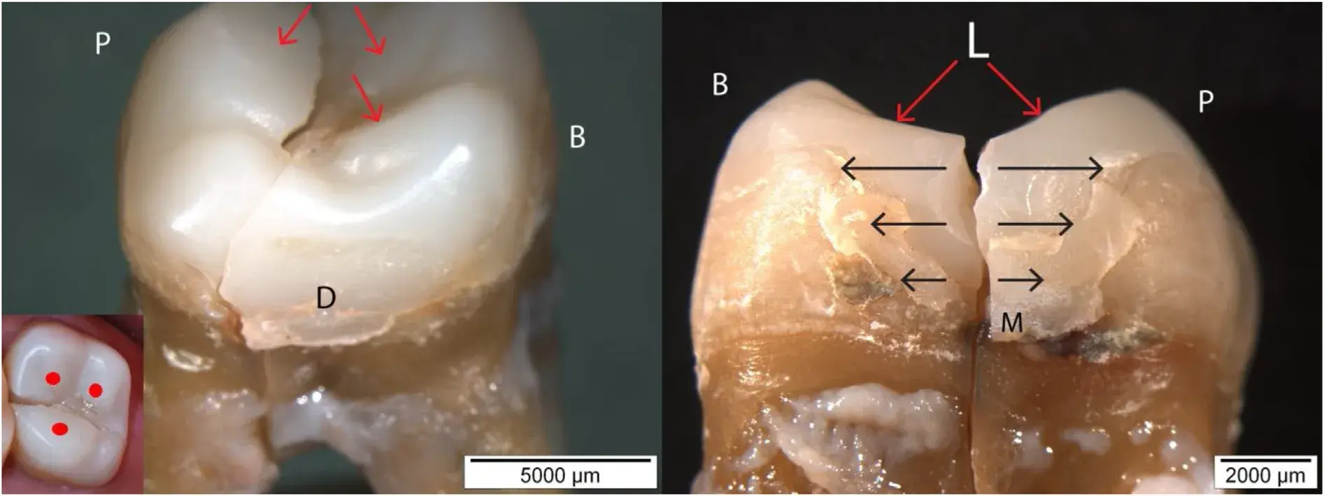 Fig. 3 – Case 1 showing a fracture mode I (crack opening) through the occlusal central groove of the composite CAD/CAM restoration. Major occlusal contacts are marked with red arrows (and dots in the inset photo) as identified by stereomicroscopy. On the side view (Mesial), the red arrows indicate the approximate applied loading (L) direction on the cuspal planes during chewing generating maximum stress levels within the central groove from which a wedge-opening fracture started.
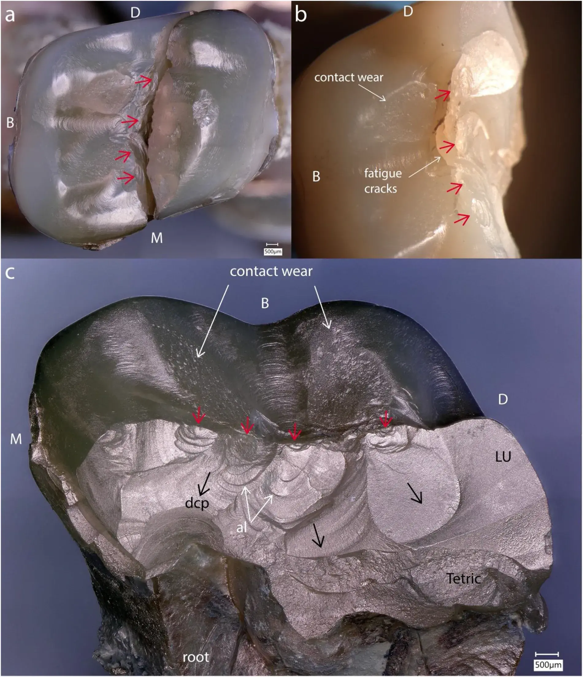 Fig. 4 – Case 1: Lava Ultimate (LU) overlay with the fracture running through the central groove. Multiple fracture origins (red arrows) (Fig. 4a, b, c) are followed by numerous concentric arrest lines (al) along the crack path (dcp) (Fig. c). Note the occlusal fatigue cracks (Fig. b) and the large wear facets on the cuspal planes. A build-up of resin composite Tetric Ceram (Tetric) constitutes a restorative base below the overlay.
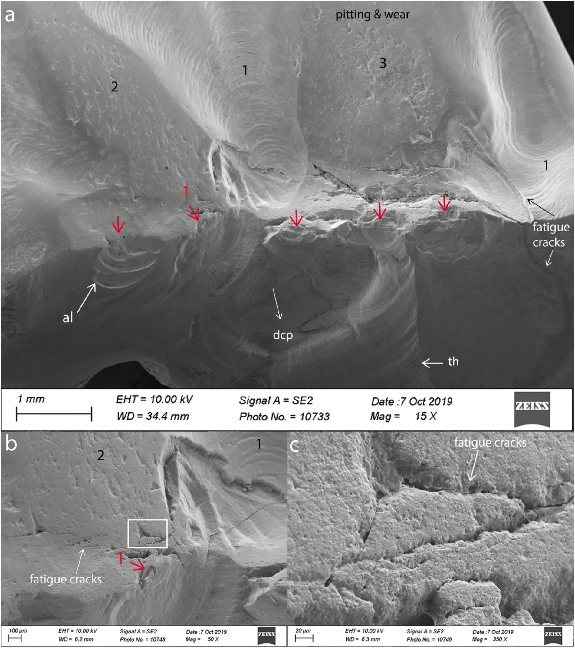 Fig. 5 – Case 1 (Lava Ultimate overlay). Multiple fracture origins (red arrows) followed by numerous concentric arrest lines (al) along the crack path (dcp). Fatigue cracks in the vicinity of the central groove are penetrating into the bulk. Zone 2 and 3 on the occlusal surface show wear contacts with a pitted appearance. Zone 1 corresponds to the unpolished CAD/CAM machining marks.
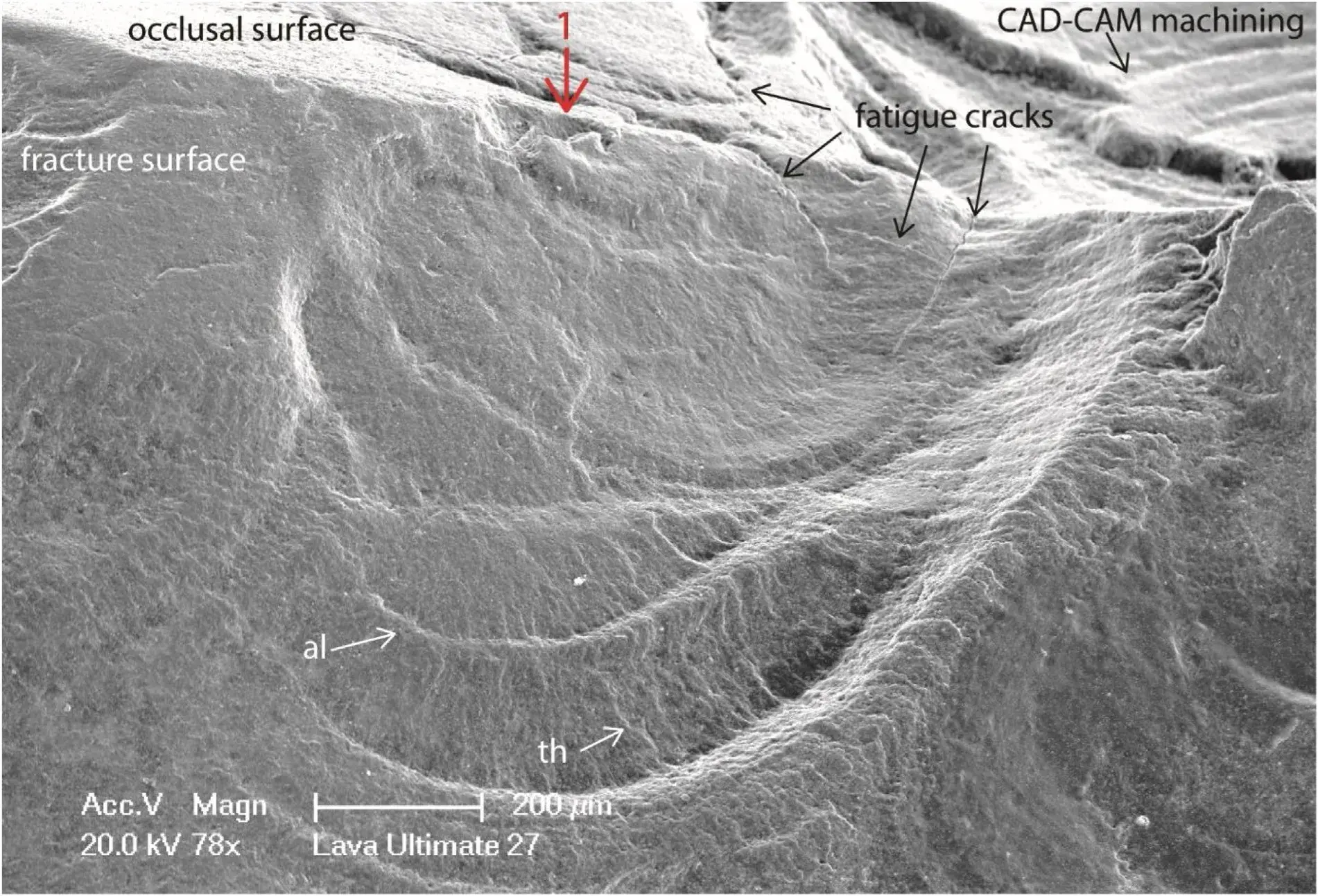 Fig. 6 – Case 1. Detailed view of fracture origin No1 in Fig. 5. Fatigue cracks are visible on the occlusal surface penetrating ∼200m deep into the bulk of the composite overlay with evidence of some crack branching at 90◦. Multiple arrest lines (al) are showing the stop and go process of the advancing crack progressing apically. Twist hackle (th) are between each arrest line.
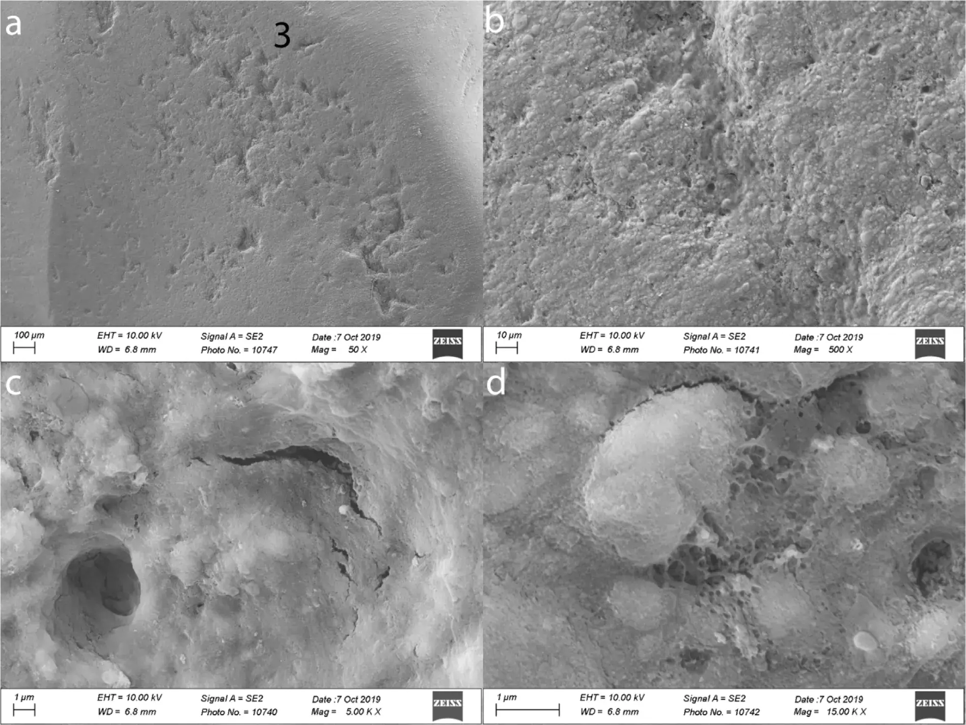 Fig. 7 – Case 1.Higher magnifications of the Lava Ultimate wear facet on the disto-buccal cuspal plane in Zone 3 (see also Fig. 5a). Such wear scars are an ongoing process of polymer matrix cracking and matrix-filler interface debonding (Fig. 7c, d) accelerating the localized loss of material and increasing the pitting.
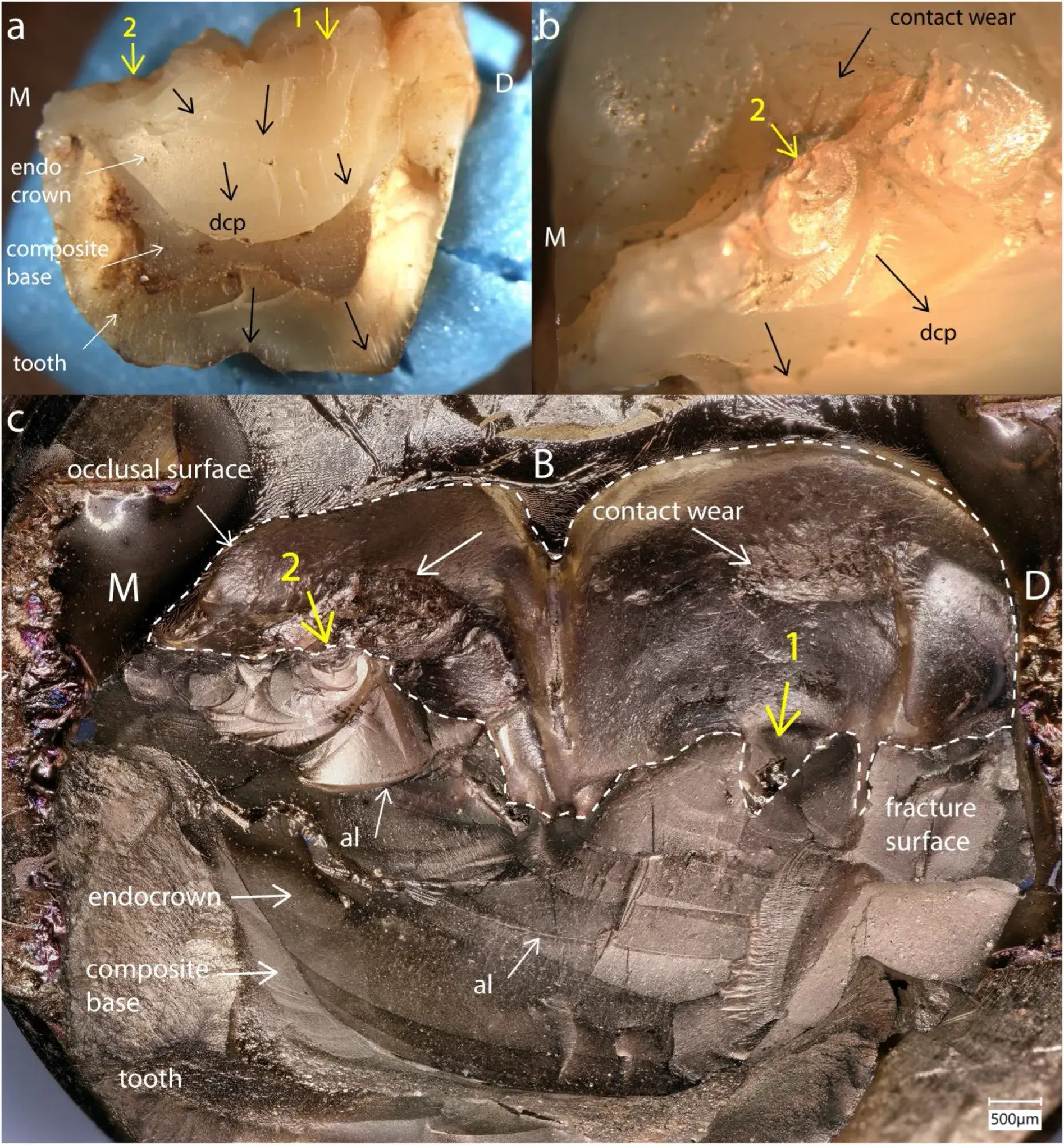 Fig. 8 – Case 2. M endocrown (Premise Indirect) recovered buccal half after 47 months of intraoral function. Two main fracture origins (yellow arrows) located on the occlusal surface are followed by many arrest lines along the crack path (dcp) on the fracture surface. Crack origin No 1 is a processing hole within the central groove of the crown (Fig. 8c). Crack origin No. 2 is connected to an occlusal contact damaged wear facet (Fig. 8b, c).
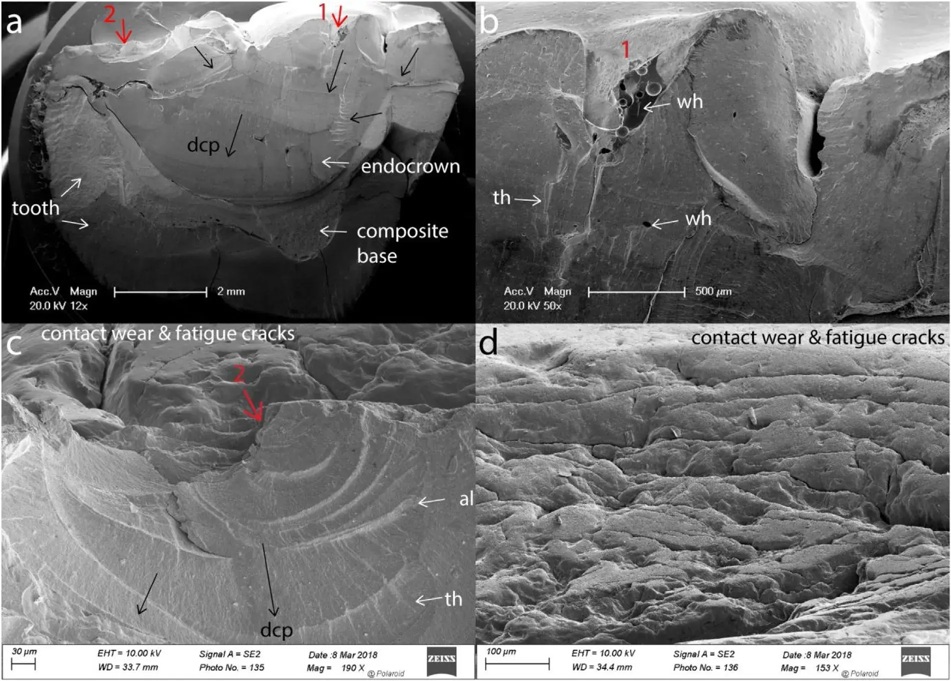 Fig. 9 – Case 2 (Premise Indirect). Details of crack origin No 1 (Fig. 9a, b), a processing hole on the occlusal surface at the central groove. Wake hackle (wh), twist hackle (th) and arrest lines (al) attest the dcp toward the tooth apex. Crack origin No 2 (Fig. 9a, c) started from a major occlusal contact (see Fig. 8b, c) containing multiple fatigue cracks from cyclic loading (Fig. 9c, d). Fracture started from one of these fatigue cracks and propagated in steps as seen from the multiple arrest lines (al) and twist hackle (th) (Fig. 9c).
Case 3: indirect layered resin-composite molar No. 26 / 14 endocrown (Premise Indirect)
The fracture of this restoration occurred after 39 months during mastication and splitthe endocrown and tooth through the central groove in a wedge opening type of fracture (Fig. 10a). For this recovered palatal (P) part we willfocus on the disto-palatal portion ofthe fracture surface, as too much ofthe restoration was lost in the mesio-palatal approximal region due to the extraction process. The disto-palatal part shows the fracture origin (yellow arrow) starting from a major occlusodistal contact wear damaged surface (Fig.10a–c) characterized by multiple fatigue cracks (Fig. 10b, c). On the fracture surface, the crack origin is related to fatigue cracks reaching up to 400m deep into the bulk (Fig. 10c). Once the fracture started, the crack path underwent several stops and starts as evidenced by the multiple semi-circular arrest lines containing fine twist hackle in between. The directions of crack propagation (dcp) are indicated by black arrows (Fig. 10a). On the distal portion, the crack moved first apically in a distal direction, then was deflected mesially, before meeting the other crack front arriving from the occluso-mesial side before resuming its propagation towards the tooth apex. Major changes in the cracking plane can be seen from Fig. 10a, c which are occurring due to various energy levels being imparted to the restoration during the cyclic chewing impacts, but also from the supporting tooth structure redirecting the crack path. The build-up composite base in the pulp chamber was not well bonded to the tooth as seen from the large spaces atthe mesial and distal tooth-resin interface (Fig. 10a).
Case 4: indirect layered resin-composite molar No. 47 / 31 endocrown (Colombus)
The clinical in situ fracture images of this case are shown in Fig. 2. The crown split through the central groove in a mode I fracture during chewing after 48 months. The recovered lingual part documented in the following 3D digital microscope and SEM images (Fig. 11) shows the endocrown bonded with a self-adhesive luting agent (RelyX Unicem) to the pulp cham- ber and tooth structure without a composite build-up layer.
Several starter cracks are indicated by yellow and red arrows on the occlusal surface within the central groove. The main crack origin (red arrow) is located on the disto-lingual cuspal plane and connected to a large oblong-shaped occlusal contact-load surface (Fig. 11a). Two smaller starter cracks (yel- low arrows) are visible on the mesio-lingual cuspal plane (Fig. 11a) and propagated towards the mesial margin of the endocrown. Close-up views of the fracture origin (red arrow) (Fig. 11b, c) show several spaced-out arrest lines (al) as well as twist hackle (th) that indicate the dcp (white arrows) was moving downwards towards the roots. The crack origin is related to a processing hole on the occlusal surface. The pitted and worn occlusal contact surface (Fig. 12a) from which the main critical crack started (Fig. 12b) contains very few microcracks in contrast to the previous Premise Indirect cases 2 and 3. Higher magnification of the fracture origin (Fig. 12b) shows a smooth surface of the processing pore, from which fracture started, different from the fatigued, pitted and worn contact surface. Higher magnifications of the pitted occlusal wear surface shows loss of composite material (Fig. 12c) but with relatively few fatigue microcracks (Fig. 12d).
Case 5: indirect layered resin-composite premolar No. 14 / 5 endocrown (Colombus)
The fracture occurred of this restoration after 15 months splitting the endocrown and part of the tooth in two through the central groove in mode failure I (Fig. 13a). The recovered palatal part shows a main fracture origin (red arrow) on the occlusal surface related to a weakening processing pore (0.5 mm in depth) (Fig. 13b, c). The internal surface of the processing pore is smooth because the resin is poorly cured due to oxygen exposure. One major arrest line (al) and many twist hackle (th) are visible on the fracture surface below the fracture origin (Fig. 13b, c). The dcp (black arrows) moves from occlusal to apical. A major occlusal contact wear surface (Fig. a) indicates a rather centered loading on the palatal cuspal plane and was not in contact with the fracture origin. The wear facet, as well as the extending fatigue crack on the occlusal surface (Fig. 13b), are further analyzed under the SEM in Fig. 14.
At low magnification (Fig. 14a) the occlusal contact wear surface shows pitting (little holes). The pitting is a result of the loss of composite and localized pull-out of filler particles during contact wear with the opposing tooth (Fig. 14b) leaving a rather smooth void in the polymer matrix. Further, very small pores within the polymer matrix contribute to the composite surface pitting (Fig. 14b). From each side of the fracture origin (Fig. 13b), three chip fractures (Fig. 14a) are seen. A fatigue crack has grown horizontally with a curvature (Fig.13b, Fig. 14a). The tip of the fatigue crack, magnified at 10,000× in Fig. 14c shows polymer cracking, crack bridging (br), transfiller fracture (tf), and filler interface debonding (fi)) including a dislodged filler particle inside the open crack. Despite the large wear contact surface, few little fatigue cracks are present compared to the findings for the previously described cases 2 and 3.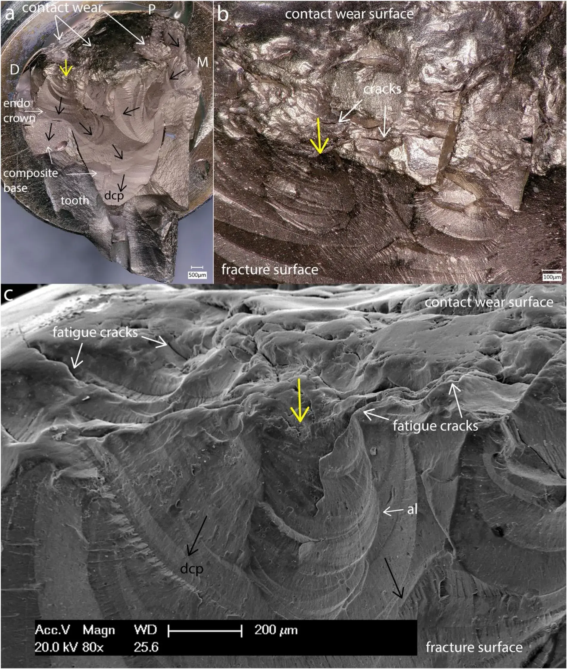 Fig. 10 – Case 3 (Premise Indirect) molar endocrown with tooth fracture after 39 months. On the recovered palatal part the failure analysis focuses on the occluso-distal fracture origin (yellow arrow) starting from a major occlusal contact damage (Fig. 10a–c) containing multiple surface fatigue cracks (Fig. 10b, c) some of which are extending up to 400m deep into the bulk (Fig. 10c). Major changes in the cracking plane can be seen from the black arrows (dcp) Fig. 10a, c. The build-up composite base in the pulp chamber was not well bonded to the tooth as seen from the large spaces at the mesial and distal tooth-resin interface.
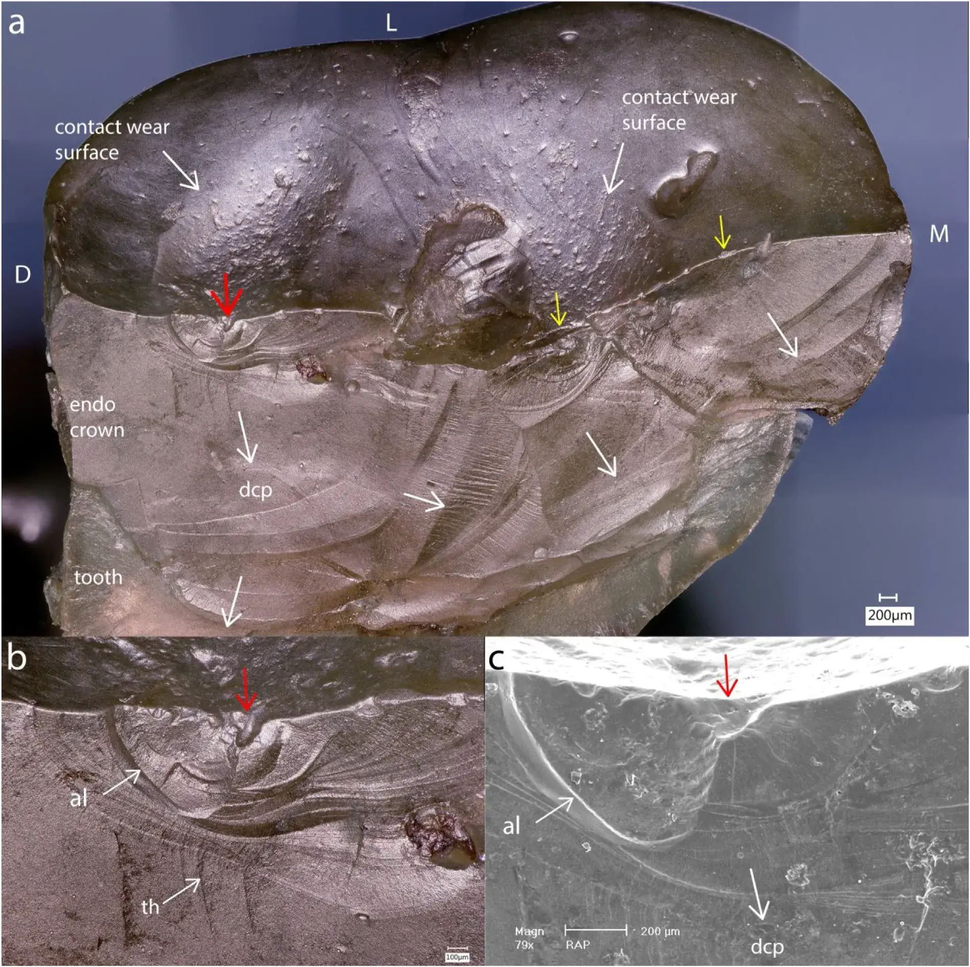 Fig. 11 – Case 4: Recovered lingual part of the Colombus endocrown (molar No. 47 / 31) (see Fig.2c) which fractured after 34 months. The main crack origin (red arrow) is related to a processing hole (Fig. 11b, c) located on the DL cuspal plane and connected to a large saucer-shaped occlusal contact surface (Fig. 11a). Two smaller starter cracks (yellow arrows) are visible on the ML cuspal plane (Fig. 11a). Multiple arrest lines (al) and twist hackle (th) indicate the dcp towards the tooth apex.
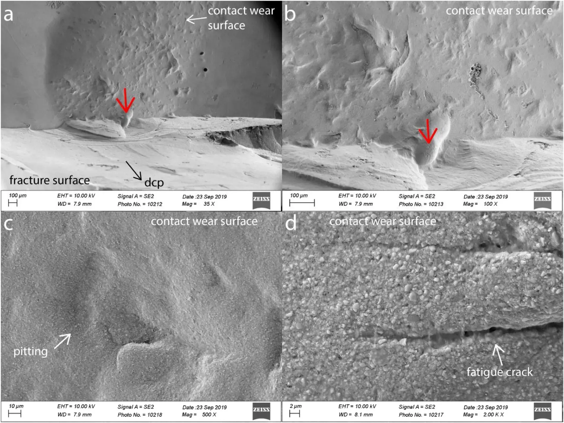 Fig. 12 – Case 4 (Colombus): SEM images of the main fracture origin described in Fig. 11. The origin is a processing pore (red arrow) (Fig. 12a, b) having a smooth surface. The pitted and worn occlusal contact surface (Fig. 12a, c) contains very few microcracks (Fig. 12d).
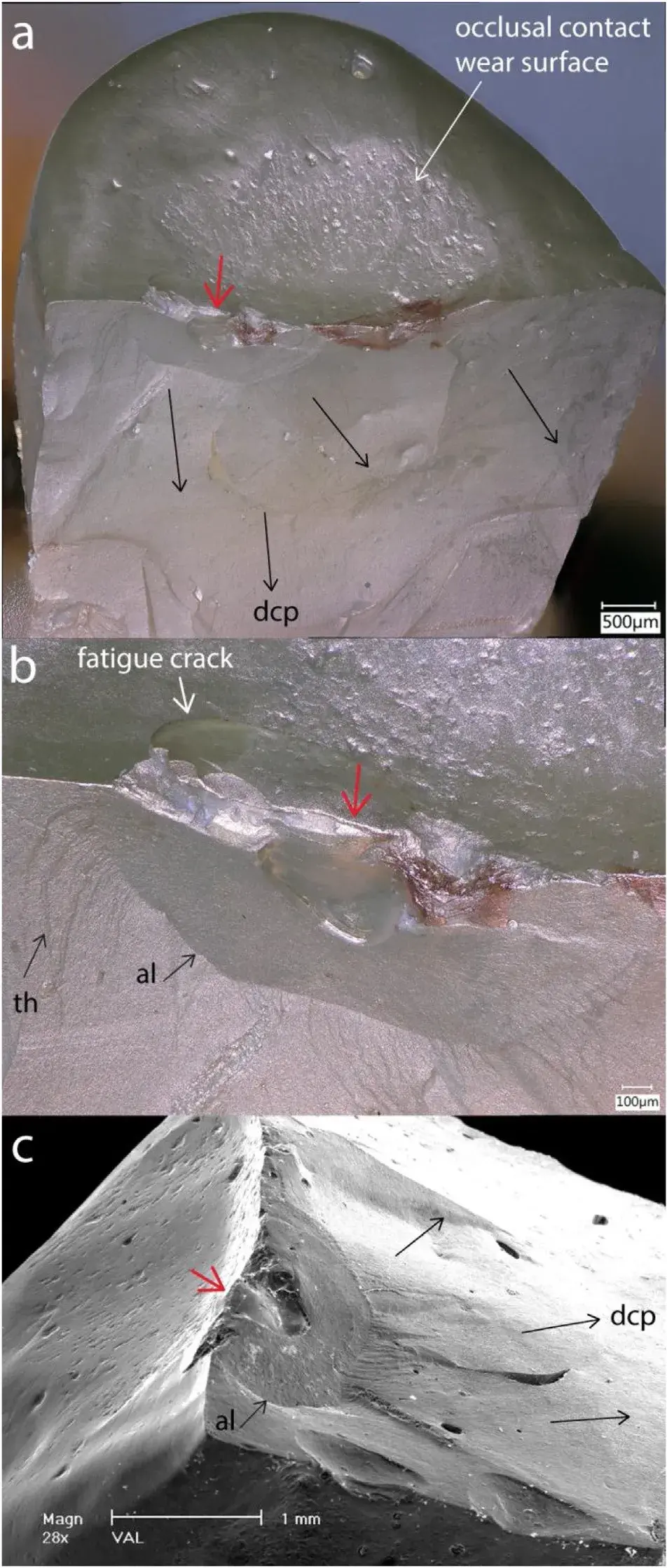 Fig. 13 – Case 5: Indirect endocrown fracture on the premolar tooth No.14 / 5 after 15 months. The recovered palatal part shows a main fracture origin (red arrow) on the occlusal surface which is a weakening processing pore. On either side of the origin are chip damages (Fig. 13b) from which a fatigue crack extends. Arrest lines (al) and twist hackle (tw) are indicating the dcp (black arrows) (Fig. 13b, c). A major occlusal contact wear surface (Fig. 13a) indicates the rather centered loading on the palatal cuspal plane. Again, the failure is a mode I wedge opening type with propagation of the crack from occlusal to apical.
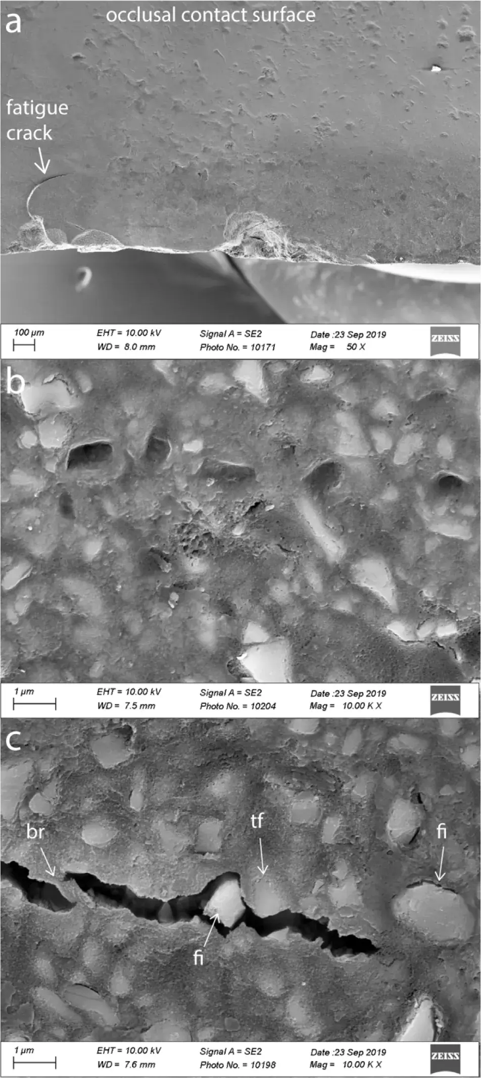 Fig. 14 – Case 5: Details of the contact wear zone reveals pull-out of the reinforcing filler particles (Fig. 14b) leaving a rather smooth void in the polymer matrix. Very small pores within the polymer matrix contribute to the overall composite surface pitting (Fig. 14a). The tip of the fatigue cracking in Fig.14a, magnified at 10,000 x in Fig. 14c, shows polymer cracking, crack bridging (br), transfiller fracture (tf), filler interface debonding (fi) including a dislodged filler particle inside the open crack.
3.2. Cuspal plane angles
Cuspal planes angles were measured for Lava Ultimate (case 1) and Colombus (case 4 and 5). Profil measurements obtained from 3D digital occlusal images are shown in Fig. 15. Fig. 15a illustrates the Lava Ultimate broken overlay. Fig. 15b indicates the profil sections made from the central groove (horizontal plane) to the cusps tips. Respective slopes for Lava Ultimate were 35◦ for the mesio-buccal (MB) and disto-buccal cusps (DB) and 50◦ for the mesio-palatal cusp (MP). Measurements for Colombus case 4 are shown in Fig. 15c. The cuspal plane angles for the lingual recovered part were respectively 35◦ for the ML and 30◦ for the DL cusp slopes on their steepest portion. Fig. 15d represents the Colombus case 5 palatal recovered part with a cuspal plane angle of 30◦. For the two Premise Indirect composite endocrowns, measurement could not be performed with sufficient confidence.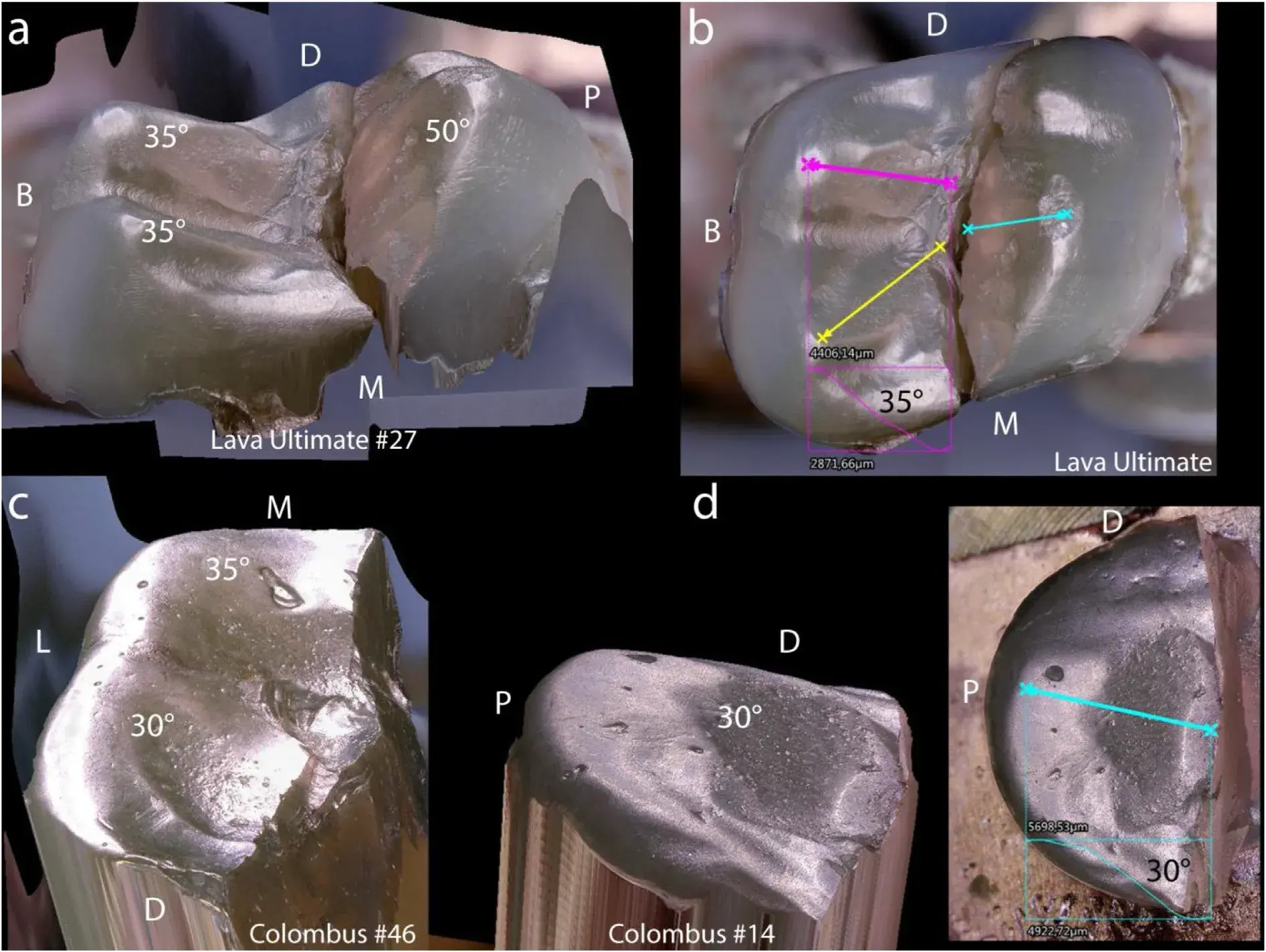 Fig. 15 – 3D representation of the recovered parts for Lava Ultimate (Fig. 15a), Colombus case 4 (Fig. 15c) and Colombus case 5 (Fig. 15d). Cuspal planes angles measured from profiles with respect to the horizontal plane of the central groove as shown in Fig. 15b, d provided angles for Lava Ulitmate of 35◦ for the MB and DB cusps, and 50◦ for the MP cusp. Colombus case 4 (Fig. 15c) had lingual cusp planes of 30◦ (DL) and 35◦ (ML) on their steepest portion. Colombus case 5 (Fig. 15d) had a palatal cusp plane of 30◦.
4. Discussion
Brittle materials such as highly filled resin composites will fail with little to no plastic deformation. Fracture often occurs catastrophically, meaning that total failure occurs in a sudden and unexpected way. But fracture, before being catastrophic, may also occur in stages in which a crack will grow in steps under cyclic loads of varying magnitudes and orientations such as during chewing, assisted by the presence of oral fluids.
Therefore, when performing a fractographic analysis on broken parts itis important describing the overall fracture pattern as well as recognizing the fracture origin(s), the source(s) from which brittle fracture began [22,31]. The fractographic failure analysis performed on four endocrowns and one overlay restored over endodontically treated teeth revealed several common key characteristics.
Firstly, all cases failed primarily in a wedge-opening mode I fracture through the central occlusal groove of the crown, splitting not only the restoration, but the supporting tooth structure as well. Secondly, in all cases multiple origins of fracture were located at the occlusal surface within or nearby the central groove. Thirdly, large contact-loading areas on cuspal planes showed signs of wear and pitting typically with some fatigue cracks. On the basis of these observations of clinical fractures, the failure processes are discussed with respect to fracture mechanics theory and factors involved in the mechanical fatigue degradation of dental resin composites.
4.1. Fatigue cracking degradation
Fatigue degradation of resin-composites has been widely explained in many key papers [29,32–34] and is the major cause of failure of a structure subjected to cyclic loading. The formation of multiple fatigue cracks, inducing a break-up of the composite structure with the resultant lowering of the mechanical properties, has been identified within the occlusal surface.
During the early stages of occlusal functioning of the restoration, cracks of subcritical sizes are formed from repeated loading at levels below the critical level for catastrophic failure of the specific material. The cracks continue to grow and branch during the cyclic loading induced by chewing. At some point in the fatigue process, these initially separated individual microcracks will connect with their neighbors, forming larger macrocracks extending deeper (i.e. radial extension) into the bulk of the resin composite restoration. This was clearly shown on the occlusal and fracture surfaces of Cases 1–3 (Figs. 5, 6, 10) where occlusal fatigue cracks penetrated and even branched in the subsurface bulk of the composite resin material.
This deterioration of the material due to surface fatigue cracking significantly lowers the ability of the resin composite to withstand further chewing loads and accelerates the process of catastrophic fracture. Because the restorations are constantly bathed in the aqueous oral environment, fluids can penetrate through the surface microcracks and be absorbed by the resin matrix. The result is some microscopic swelling of the resin matrix along with the formation of interfacial stress and hydrolysis ofthe silane-mediated bond between the inorganic filler and the polymer matrix [29,32,33,35]. Evidence of water uptake of 43 g/mm3 after 2 months of intraoral function was measured on recovered fractured parts of Lava Ultimate crowns bonded to zirconia implant abutments [19]. Thus, crack formation may result from a combination of external (masticatory) damage accumulation, internal residual stresses in the microstructure of the composite material from processing as well as from hydrolytic degradation [19,35]. Evidence for the deterioration of the properties of the composite has been shown in several in vitro studies. For example, the Colombus composite used in Case 4 and 5, experienced a loss of strength of 62% from its static characteristic flexural strength value of S0 = 145 MPa when subjected to a rotating-bending cantilever fatigue test (16.7 Hz and 106 cycles) under moist conditions. The 50% survival stress (S50) was 54.6 MPa [36].
Belli [37] showed a 48% reduction from the initial flexural strength value of 123 MPa for Lava Ultimate, the material used in case 1, when the composite was exposed to 104 cycles in an in vitro four-point-bending cyclic fatigue test. In another study by Wendler [14], Lava Ultimate CAD/CAM disks lost close to 40% of their initial strength when subjected to 105 cycles of biaxial loading (ball-on-three-balls). Other studies have demonstrated a loss of strength and toughness during cyclic fatigue under hydrolytic conditions with the magnitude being influenced by the filler volume fraction, filler particle sizes, quality of the cross-linking of the matrix and chemistry of the monomers [15,32,38–43]. The clinical fractures for cases 1–5 occurred after respectively 4, 47, 39, 48 and 15 months. Assuming 3 periods of 15 min chewing per day at a rate of 60 cycles per minute at 1 Hz [44], the respective loading cycles would be 324,000× (Case 1), 3,807,000× (Case 2), 3,159,000× (Case 3), 3,888,000× (Case 4) and 1,215,000× (Case 5). The extent of the loss of strength created by the clinical fatigue degradation in each of the clinical cases presented cannot be expressed with certainty, but considering the fatigue-induced micro/macro cracks visible on the occlusal surface, as well as the large contact wear facets formed, one can hypothesize that these restorations failed more rapidly than expected due to their accumulated structural degradation.
Fatigue fracture will occur over a variety of crack sizes as a function of applied stresses. Hence, failure from a small crack will occur under high applied stress, whereas, fracture initiated from larger cracks will occur under lower applied stress [29].
4.2. Mode I fracture (crack opening mode) and fracture surface
Fracture mechanics are used to study fracture processes in materials that are either brittle or have a ductile-brittle behavior with substantial plasticity. The linear elastic fracture mechanics approach (LEFM) deals with brittle fracture, defined as originating from a sharp crack resulting from processing or from fatigue cracking under functional cyclic loading. These small sharp cracks on the surface can rapidly grow when placed in tension or shear under varying amplitude and alternating cyclic loads until reaching a critical length at which the material will fracture catastrophically. Dental particulate-reinforced resin composites are highly brittle in their behavior [45],thus allowing application of LEFM principles to study their fracture phenomena.
Mode I fracture corresponding to a tensile stress normal to a plane of cracking was observed for all five clinical failure cases. A crack opening fracture mode I occurred from the wedge-opening effect of the loaded cusps from the antagonist tooth once the critical stress intensity level was reached at the fracture origin. Nevertheless, the loading of the crowns cuspal planes during the chewing cycles may have some in-plane shear mode II loading acting on the crack at the same time it is under opening mode I loading. The initial crack or flaw may also be oriented at an angle with respect to the applied cuspal load. Thus, it is very likely that a combination of loading conditions in mixed mode I (normal) and mode II (shear) have acted in the initial crack propagation. This may be seen from the different fracture planes after major arrest lines as well as the presence of twist hackle formed under mode I/II loadings.
Attempts to deduce fracture stress using quantitative fractography would be very speculative as the critical crack length is difficult to identify for several reasons, including loss of information due to broken off material at the origin, possible R-curve behavior ofthe composite, and the presence of numerous fracture origins. However, evidence of deep penetrating fatigue cracks into the bulk (400 m up to 1 mm) indicates that the restorations had been subjected to quite heavy loads during chewing.
Arrest lines are observed from iterative loading creating incremental crack growth [31]. On the fracture surfaces, closely spaced-out concentric arrest lines next to the crack origins are indicators of a momentary stop of the crack propagation. After resuming propagation, the crack has slightly changed planes due to a change in the axis of principle tension [31].We assume that during cyclic fatigue loading, distinct loading events reach a threshold energy that causes the crack to propagate in stages, though the energy associated with any of these events is not sufficiently high to cause catastrophic failure. This may be an explanation for these numerous regularly spaced-out sharp lines visible in all molar fractures (cases 1–4), regardless of which resin composite reconstruc- tion material was used.
Manually layered endocrowns are prone to fabrication defects, mainly air bubbles or pores. Hence, both Colombus cases 4 and 5 as well as Premise indirect (case 3, origin No.1) had processing pores of ∼0.5 mm deep, which acted as crack origins. These small cavities (i.e. holes) were all located at the occlusal surface next to the central isthmus and sometimes in direct relation with contact loading surface degradation.
These occlusal surface cavities, which remain unpolished after curing, may also be incompletely polymerized due to the presence of an oxygen inhibited layer on their surface. Hence, these processing defects will serve as the weakest link, combined with localized stress concentration along the central groove from cuspal planes wedge opening loadings. Evidence for this exists as the degree of conversion for Colombus composite (with a bisGMA/UDMA matrix) has been measured by FTIR to be 60% on the surface and 73% in the bulk [46].
A fracture toughness of KIc = 0.56 MPa√m has been reported for Colombus using the Brazilian disk test [46], whereas for the heat-cured CAD/CAM block of Lava Ultimate, toughness values of KIc = 1.14 MPa√m (compact tension test) [14], and 0.91 MPa√m (notchless triangular prism NTP) [47] were reported.
The manufacturer’s product description indicates a KIc = 2.02 MPa√m (SEVNB). It is assumed that the fracture toughness for Premise Indirect composite will lie between that of Colombus and Lava Ultimate, as it has a similar chemical composition though a slightly higher filler content as compared with Colombus, but is, also light activated followed by heat polymerization with a degree of conversion of 58% after 24 h [48]. These differences in toughness however have not prevented the catastrophic clinical fracture including the loss of the tooth.
The preferential path followed by the growing and propagating crack from the occlusal fatigued surface demonstrated a mixture of polymer matrix cracking, interfacial debonding, cluster/filler fracture and even crack bridging, all of which representtypicaltoughening mechanisms seen in microhybrid as well as nanofilled composites [49].
The fact that dental resin composites will degrade in their mechanical properties with major losses of strength (40–50%) after being subjected to only 104−5 cycles under fatigue testing [14,37] requires care in material selection as well as crown design. Many factors will increase stress concentration and crack formation, such as cusp angles and anatomical grooves in a V-notch shape as discussed in the next section.
4.3. Cusp angles and central groove notch design
A recent publication by Shahmoradi [50] showed via FE models of a monolithic crown design that cusp angles, the crown’s central groove notch design (sharp vs round) and the thickness of the restoration greatly influence the crack-initiation load leading to fracture. Their models clearly demonstrated that cusp angles ≥ 40◦ (measured from the horizontal plane of the central groove to the cuspal plane) create stress concentrations in the center of the central groove for a contact load of 150 N and a crown thickness of 1.5 mm. In our research, the cusp angles of the recovered fractured crown parts were between 30–35◦ in most of the cases, except for the palatal cusp of Lava Ultimate which was indeed quite steep (i.e. 50◦). The sharpness of the central groove notch could not be verified, as portions of material had been lost, but for a CAD/CAM machined crown the central groove is never sharp due to the limitations of the bur dimensions and machining process.
However, for the artisanal made crowns, depending on the layering technique used in the laboratory, the central isthmus of the crowns can be sharp and incorporate some large processing pores which may serve as crack origins. The final message from FEM literature is clear: for monolithic materials (all except zirconia) cusp slopes of 20−30◦ (from a horizontal groove plane) as well as a rounded central isthmus should be incorporated into the design of the crown [50–52].
4.4. Composite composition and occlusal surface degradation
The contact wear zones on the occlusal surface with the antagonist tooth were easily identified with the stereomicroscope. Whether there was excessive wear cannot be concluded as no initial evaluation was available. However, the microscopic analysis of the occluding surface showed local degradation through pitting, wear and sometimes micro/macro cracking. The differences between the five presented cases may be discussed in light of the compositional and processing differences of the materials.
Increasing the filler content with nano-particles and clusters in the micro-sized range, along with a highly cross-linked polymer matrix due to the use of high pressure and heat for improving the degree of conversion, increases toughness and stiffness [47,53]. Hence, the resin composite will, in such formulations, behave in a more brittle manner as matrix deformation is limited.
This may explain the presence of multiple micro and macro cracks in the vicinity of the isthmus next to the fracture site for Lava Ultimate. After 4 months of intraoral function, Lava Ultimate overlay showed pitted contact wear surfaces resulting from breaking-off of micro clusters of filler particles, leaving multiple localized deep craters on the occlusal surface at the contact wear region. Little to no microcracking was detected within the large sliding contact surfaces, confirming research findings from a previous sliding contact test [54] for this material. Unfortunately, no information is available regarding the antagonist tooth involved in the occlusal contact.
The large and smooth looking oblong-shaped contact wear surfaces for both Colombus cases (4 and 5) may be attributed to some initial occlusal adjustments which were well polished, as no obvious scratches remained on the surface. The pitted contact wear surface looked similar to that of the Lava Ultimate restoration. The antagonist contacting tooth has enamel cusps for Case 4 as verified from available X-Rays. However, no information is available regarding the antagonist tooth for Case 5.
Premise Indirect (Case 2 and 3), a highly filled and crosslinked resin composite (84 wt.% [55]), showed very rough occlusal contact surfaces with extensive crack damages. The existence of multiple wide open cracks most probably are attributed to higher contact pressure and friction occurring over 3 years of mechanical function, accelerating the formation of a surface and sub-surface crack network, drastically lowering the lifetime of the restoration. The extensive roughness of the contact wear surfaces is due to an ongoing loss of reinforcing filler particles accompanied by breaking-off of portions of the polymer matrix, leaving deep open cracks. The available X-Rays for both cases 2 and 3 showed again antagonist teeth with enamel cusps.
Allthree ofthe resin composite materials have similar elastic moduli constants (around 11−12 GPa) and similar wt.% of filler particles (77−84 wt.%) [12,36,56]. Some differences certainly exist in terms of degree of conversion which adds to the pitting and micro / macro crack formation. But the dominant degradation process will come from the intraoral chewing conditions, contact pressure, occlusion impacts and frictional wear. The fact that the strongest, toughest and best cured material, Lava Ultimate, failed prematurely after 4 months is related to the wedge-opening forces acting on the relatively steep cuspal planes, and the fact that it was an overlay with a thickness ranging between 2.3–2.8 mm, contrary to the more voluminous and thicker endocrowns (∼3−4 mm) in the other four cases.
4.5. Clinical considerations
Fracture of direct layered composite restorations on posterior teeth has been reported to be an important reason for failure with a risk increase from the second year onward [20].
For indirect CAD/CAM or laboratory layered resin composite endocrowns, there are no clinical trial results available. It is therefore more difficult to be more specific regarding the failure analysis with a limited number of fracture cases. In addition, all five cases in this study were located in dif- ferent teeth and presented different anatomies. Despite all being classifiable as adhesive restorations to ETT, they were all of different thicknesses as a result of their different designs (overlay vs endocrown) or extensions of the endocore inside the pulp chambers. Nevertheless, one should consider the effectiveness of ETT with resin composites as the choice of reconstruction material in high stress regions in posterior teeth.
As mentioned in the introduction, the use of novel resin composites for crown reconstructions on molars, have been suggested [3,11]. The main argument in favor of resin composites vs ceramics are costs, ease of fabrication, handling and repair in case of partial fracture.
Overall, strength, fracture toughness, and elastic constants were not very different among the three resin composites. All resin composites will degrade as soon as they are exposed to water and cyclic fatigue which is the case in the oral environment. This shows that for such large restorations improvementin toughness due to processing has not been sufficient to avoid catastrophic fracture. Although toughness is a highly relevant property to characterize dental resin composite materials [27], only a weak correlation was found relating toughness and clinical fractures in a major systematic review of resin composites on posterior teeth [57]. Linear elastic properties (E, flexural , KIc) were also shown to have limited clinical relevance. Initial properties were better associated with microstructural features such as filler particles and particle clusters, whereas fatigue resistance depended more on the polymeric matrix [15].
The toughest and strongest material of the analyzed failure cases was Lava Ultimate which since 2015 is no longer indicated by the manufacturer for crowns because of debonding issues. The fractured overlay was performed in early 2013, before the revised recommendation was issued by 3M.
Colombus which was on the market in the year 2000, was made specifically for indirect molar restorations. Endocrowns were not specifically mentioned. Cases 4 and 5were performed in 2002 and the choice to use this material to reconstruct an ETT was made by the clinician using available adhesive luting techniques. Premise Indirect has been indicated for crowns and bridges with, however, the specific request by the manufacturer to incorporate their polyethylene braided fibers to reinforce the restoration. This was not done in the two fractured molar cases (2 and 3). Fiber reinforcement is meant to strengthen the reconstruction and provide toughening mechanisms of crack arrest or deflection. It cannot be said whether the fractured molar reconstructions would have survived or at least not fractured vertically with ultimately the loss of the tooth had fibers been used in these cases. Nevertheless, the positioning of the fiber bundles or net is crucial with respect to the crown’s thickness. A technical report on how to reconstruct endodontically treated teeth with a resin composite build-up of the pulp chamber, followed by a fiber network and then an adhesively bonded CAD/CAM resin composite overlay was described by Rocca [58]. Deep location of a glass-fiber net (StickNet) just above the composite pulp chamber containing the core build-up, was shown to be inefficient to stop the vertical detrimental fracture of Lava Ultimate overlays of 3 mm thickness, as well as the tooth root, although some partial crack deviation at the tooth had occurred [59]. Considering that all the fractures analyzed fractographically indicated a crack origination at the central isthmus, a more occlusal positioning of the fiber net above a dome-shape pulp chamber composite build-up could better serve the purpose of crack arrest or deflection and avoid the loss of the tooth in the case of fracture during mastication.
It is beyond the scope of this paper to discuss which material for endocrown reconstruction would be most appropriate for endodontically treated teeth [3,4,11,60]. Unfortunately, clinical evidence on the suitability of chairside resin composite based CAD/CAM blocks is completely lacking. Despite this lack of evidence, manufacturers today broadly indicate their materials for the preparation of single crowns. The endocrown indication is not always specified in respective instructions for use.
Attempts to compare the performance of resin composites restorations (inlays, onlays, overlays) over ceramics using a meta-analysis remained inconclusive due to the lack of standardization or criteria reported [61].
Regarding ceramics, lithium disilicate glass ceramics would represent the material of choice, as they can be well bonded to tooth structure and have a good compromise in terms of strength (300−400 MPa), fracture toughness (2.2–3.0 MPa√m) and elastic modulus (100 MPa).
It is worth reemphasizing that the dominant forces on the cuspal planes of such reconstructions are critical, as these are wedge-opening forces that form detrimental cracks at the central groove. Hence, reconstruction designs possessing less steep cusp slopes, rounded central grooves and occlusal contact management to relieve excessive chewing contacts should be the standard. Certainly, based on our findings, development of a resin composite material offering improved wear and fatigue resistance, especially in the occlusally loaded contact regions, is desirable.
You have the opportunity to gather more in-depth information about indirect tooth restoration on our website.
5. Conclusion
Fractographic failure analysis of recovered clinically fractured molars and premolar endocrowns and overlay on endodontically treated teeth was successfully performed with stereomicroscopy, 3D digital microscopy and SEM analysis.
Fracture origins were located nearby the crown’s central isthmus on the occlusal surfaces with catastrophic crack propagation towards the root, splitting the restoration and the tooth. The resin composite reconstructions failed from a combination of several factors: (a) fatigue degradation from cyclic loading, (b) wedge opening mode I fracture from loadings on cuspal planes, and (c) critical stresses concentrating in the vicinity ofthe central isthmus which acted as sharp V-notches.
Clear evidence of contact wear with pitting and sometimes extensive fatigue cracking indicated a brittle behavior under functional loading. More clinical trials and fractographic failure analyses are needed to better understand possible clinical outcome limitations of the use of resin composites for reconstructions of severely damaged endodontically treated teeth.
List of authors:
Carlo M. Saratti, Giovanni T. Roccaa, Stéphane Durual, Ulrich Lohbauer, Jack L. Ferracane, Susanne S. Scherrer
References
Rocca GT, Krejci I. Crown and post-free adhesive restorations for endodontically treated posterior teeth: from direct composite to endocrowns. Eur J Esthet Dent 2013;8:156–79.
Biacchi GR, Mello B, Basting RT. The endocrown: an alternative approach for restoring extensively damaged molars. J Esthet Restor Dent 2013;25:383–90.
Carvalho MA, Lazari PC, Gresnigt M, Del Bel Cury AA, Magne P. Current options concerning the endodontically-treated teeth restoration with the adhesive approach. Braz Oral Res 2018;32:e74.Sedrez-Porto JA, Rosa WL, da Silva AF, Munchow EA, Pereira-Cenci T. Endocrown restorations: a systematic review and meta-analysis. J Dent 2016;52:8–14.
Belleflamme MM, Geerts SO, Louwette MM, Grenade CF, Vanheusden AJ, Mainjot AK. No post-no core approach to restore severely damaged posterior teeth: an up to 10-year retrospective study of documented endocrown cases. J Dent 2017;63:1–7.Otto T, Mormann WH. Clinical performance of chairside CAD/CAM feldspathic ceramic posterior shoulder crowns and endocrowns up to 12 years. Int J Comput Dent 2015;18:147–61.
Bindl A, Mormann WH. Clinical evaluation of adhesively placed Cerec endo-crowns after 2 years–preliminary results. J Adhes Dent 1999;1:255–65.Bernhart J, Brauning A, Altenburger MJ, Wrbas KT. Cerec3D endocrowns–two-year clinical examination of CAD/CAM crowns for restoring endodontically treated molars. Int J Comput Dent 2010;13:141–54.
da Cunha LF, Gonzaga CC, Pissaia JF, Correr GM. Lithium silicate endocrown fabricated with a CAD-CAM system: a functional and esthetic protocol. J Prosthet Dent 2017;118:131–4.
Tzimas K, Tsiafitsa M, Gerasimou P, Tsitrou E. Endocrown restorations for extensively damaged posterior teeth: clinical performance of three cases. Restor Dent Endod 2018;43: e38.
Mainjot AK, Dupont NM, Oudkerk JC, Dewael TY, Sadoun MJ. From artisanal to CAD-CAM blocks: state of the art of indirect composites. J Dent Res 2016;95:487–95.
Belli R, Wendler M, de Ligny D, Cicconi MR, Petschelt A, Peterlik H, et al. Chairside CAD/CAM materials. Part 1: measurement of elastic constants and microstructural characterization. Dent Mater 2017;33:84–98.
Wendler M, Belli R, Petschelt A, Mevec D, Harrer W, Lube T, et al. Chairside CAD/CAM materials. Part 2: flexural strength testing. Dent Mater 2017;33:99–109.
Wendler M, Belli R, Valladares D, Petschelt A, Lohbauer U. Chairside CAD/CAM materials. Part 3: cyclic fatigue parameters and lifetime predictions. Dent Mater 2018;34:910–21.
Belli R, Petschelt A, Lohbauer U. Are linear elastic material properties relevant predictors of the cyclic fatigue resistance of dental resin composites? Dent Mater 2014;30:381–91.
Rocca GT, Sedlakova P, Saratti CM, Sedlacek R, Gregor L, Rizcalla N, et al. Fatigue behavior of resin-modified monolithic CAD-CAM RNC crowns and endocrowns. Dent Mater 2016;32:e338–50.
Shu X, Mai QQ, Blatz M, Price R, Wang XD, Zhao K. Direct and Indirect Restorations for Endodontically Treated Teeth: A Systematic Review and Meta-analysis, IAAD 2017 Consensus Conference Paper. J Adhes Dent 2018;20:183–94.
Miura S, Kasahara S, Yamauchi S, Katsuda Y, Harada A, Aida J, et al. A possible risk of CAD/CAM-produced composite resin premolar crowns on a removable partial denture abutment tooth: a 3-year retrospective cohort study. J Prosthodont Res 2019;63:78–84.
Lohbauer U, Belli R, Cune MS, Schepke U. Fractography of clinically fractured, implant-supported dental computer-aided design and computer-aided manufacturing crowns. SAGE Open Med Case Rep 2017;5, 2050313X17741015.
Opdam NJ, van de Sande FH, Bronkhorst E, Cenci MS, Bottenberg P, Pallesen U, et al. Longevity of posterior composite restorations: a systematic review and meta-analysis. J Dent Res 2014;93:943–9.
Bayne SC. Correlation of clinical performance with’ in vitro tests’ of restorative dental materials that use polymer-based matrices. Dent Mater 2012;28:52–71.
Scherrer SS, Lohbauer U, Della Bona A, Vichi A, Tholey MJ, Kelly JR, et al. ADM guidance-Ceramics: guidance to the use of fractography in failure analysis of brittle materials. Dent Mater 2017;33:599–620.
Quinn JB, Quinn GD, Kelly JR, Scherrer SS. Fractographic analyses of three ceramic whole crown restoration failures. Dent Mater 2005;21:920–9.
Scherrer SS, Quinn GD, Quinn JB. Fractographic failure analysis of a Procera AllCeram crown using stereo and scanning electron microscopy. Dent Mater 2008;24:1107–13.
Scherrer SS, Quinn JB, Quinn GD, Kelly JR. Failure analysis of ceramic clinical cases using qualitative fractography. Int J Prosthodont 2006;19:185–92.
Heintze SD, Faouzi M, Rousson V, Ozcan M. Correlation of wear in vivo and six laboratory wear methods. Dent Mater 2012;28:961–73.
Ilie N, Hilton TJ, Heintze SD, Hickel R, Watts DC, Silikas N, et al. Academy of dental materials guidance-resin composites: part I-Mechanical properties. Dent Mater 2017;33:880–94.
Ferracane JL, Hilton TJ, Stansbury JW, Watts DC, Silikas N, Ilie N, et al. Academy of Dental Materials guidance-Resin composites: part II-Technique sensitivity (handling, polymerization, dimensional changes). Dent Mater 2017;33:1171–91.
Baran G, Boberick K, McCool J. Fatigue of restorative materials. Crit Rev Oral Biol Med 2001;12:350–60.
Kruzic JJ, Arsecularatne JA, Tanaka CB, Hoffman MJ, Cesar PF. Recent advances in understanding the fatigue and wear behavior of dental composites and ceramics. J Mech Behav Biomed Mater 2018;88:504–33.
Quinn GD. A NIST recommended practice guide: fractography of ceramics and glasses. Special publication (NIST SP) 960-16e3. Gaithersburg, MD: National Institute of Standards and Technology; 2020,
Lohbauer U, Belli R, Ferracane JL. Factors involved in mechanical fatigue degradation of dental resin composites. J Dent Res 2013;92:584–91.
Awaja F, Zhang SN, Tripathi M, Nikiforov A, Pugno N. Cracks, microcracks and fracture in polymer structures: formation, detection, autonomic repair. Prog Mater Sci 2016;83: 536–73.
Arola D. Fatigue testing of biomaterials and their interfaces. Dent Mater 2017;33:367–81.
Ferracane JL. Hygroscopic and hydrolytic effects in dental polymer networks. Dent Mater 2006;22:211–22.
Scherrer SS, Wiskott AH, Coto-Hunziker V, Belser UC. Monotonic flexure and fatigue strength of composites for provisional and definitive restorations. J Prosthet Dent 2003;89:579–88.
Belli R, Geinzer E, Muschweck A, Petschelt A, Lohbauer U. Mechanical fatigue degradation of ceramics versus resin composites for dental restorations. Dent Mater 2014;30:424–32.
Lohbauer U, Frankenberger R, Kramer N, Petschelt A. Time-dependent strength and fatigue resistance of dental direct restorative materials. J Mater Sci Mater Med 2003;14:1047–53.
Lohbauer U, Frankenberger R, Kramer N, Petschelt A. Strength and fatigue performance versus filler fraction of different types of direct dental restoratives. J Biomed Mater Res B Appl Biomater 2006;76:114–20.
Lohbauer U, Rahiotis C, Kramer N, Petschelt A, Eliades G. The effect of different light-curing units on fatigue behavior and degree of conversion of a resin composite. Dent Mater 2005;21:608–15.
Lohbauer U, von der Horst T, Frankenberger R, Kramer N, Petschelt A. Flexural fatigue behavior of resin composite dental restoratives. Dent Mater 2003;19:435–40.
Shah MB, Ferracane JL, Kruzic JJ. R-curve behavior and micromechanisms of fracture in resin based dental restorative composites. J Mech Behav Biomed Mater
2009;2:502–11.Shah MB, Ferracane JL, Kruzic JJ. R-curve behavior and toughening mechanisms of resin-based dental composites: effects of hydration and post-cure heat treatment. Dent Mater 2009;25:760–70.
Wiskott HW, Nicholls JI, Belser UC. Fatigue resistance of soldered joints: a methodological study. Dent Mater 1994;10:215–20.
Quinn JB, Quinn GD. Material properties and fractography of an indirect dental resin composite. Dent Mater 2010;26:589–99.
Scherrer SS, Botsis J, Studer M, Pini M, Wiskott HW, Belser UC. Fracture toughness of aged dental composites in combined mode I and mode II loading. J Biomed Mater Res 2000;53:362–70.
Ruse ND, Sadoun MJ. Resin-composite blocks for dental CAD/CAM applications. J Dent Res 2014;93:1232–4.
Malta DA, Magne P, Monteiro-Junior S. Bond strength and monomer conversion of indirect composite resin restorations, Part 1: light vs heat polymerization. J Adhes Dent 2014;16:517–22.
Shah MB, Ferracane JL, Kruzic JJ. Mechanistic aspects of fatigue crack growth behavior in resin based dental restorative composites. Dent Mater 2009;25:909–16.
Shahmoradi M, Wan B, Zhang Z, Wilson T, Swain M, Li Q. Monolithic crowns fracture analysis: the effect of material properties, cusp angle and crown thickness. Dent Mater 2020;36:1038–51.
Sornsuwan T, Ellakwa A, Swain MV. Occlusal geometrical considerations in all-ceramic pre-molar crown failure testing. Dent Mater 2011;27:1127–34.
Sornsuwan T, Swain MV. Influence of occlusal geometry on ceramic crown fracture; role of cusp angle and fissure radius. J Mech Behav Biomed Mater 2011;4:1057–66.
Phan AC, Tang ML, Nguyen JF, Ruse ND, Sadoun M. High-temperature high-pressure polymerized urethane dimethacrylate-mechanical properties and monomer release. Dent Mater 2014;30:350–6.
Wendler M, Kaizer MR, Belli R, Lohbauer U, Zhang Y. Sliding contact wear and subsurface damage of CAD/CAM materials against zirconia. Dent Mater 2020;36:387–401.
Soanca A, Roman A, Moldovan M, Perhaita I, Tudoran LB, Rominu M. Study on thermal behaviour, structure and filler morphology of some indirect composite resins. Dig J Nanomater Bios 2012;7:1071–81.
Rocca GT, Gregor L, Sandoval MJ, Krejci I, Dietschi D. In vitro evaluation of marginal and internal adaptation after occlusal stressing of indirect class II composite restorations with different resinous bases and interface treatments. Post-fatigue ¨ adaptation of indirect composite restorations¨. Clin Oral Investig 2012;16:1385–93.
Heintze SD, Ilie N, Hickel R, Reis A, Loguercio A, Rousson V. Laboratory mechanical parameters of composite resins and their relation to fractures and wear in clinical trials-A systematic review. Dent Mater 2017;33:e101–14.
Rocca GT, Rizcalla N, Krejci I. Fiber-reinforced resin coating for endocrown preparations: a technical report. Oper Dent 2013;38:242–8.
Rocca GT, Saratti CM, Cattani-Lorente M, Feilzer AJ, Scherrer S, Krejci I. The effect of a fiber reinforced cavity configuration on load bearing capacity and failure mode of endodontically treated molars restored with CAD/CAM resin composite overlay restorations. J Dent 2015;43:1106–15.
Magne P, Knezevic A. Influence of overlay restorative materials and load cusps on the fatigue resistance of endodontically treated molars. Quintessence Int 2009;40:729–37.
Aktas G, Yerlikaya H, Akca K. Mechanical failure of endocrowns manufactured with different ceramic materials: an in vitro biomechanical study. J Prosthodont 2018;27: 340–6.