en
Silicone key device for maxilla orientation and occlusal plane recording in a digital workflow
14
14 min read
03 April 2023
Abstract. This article describes a technique for recording the maxilla’s orientation in esthetically driven oral rehabilitation and transferring its position by using computer-aided design and computer-aided manufacturing (CAD-CAM) technology. The protocol uses a Fox plane and a bubble level to orient an addition silicone key of the maxilla parallel to the occlusal reference plane. The silicone reference key was scanned, superimposed over the maxilla intraoral standard tessellation language (STL) file, and adequately oriented in a CAD software program.
Digital techniques and procedures are replacing analog ones in an unprecedented manner,with advantages that include time efficiency, reliability, repeatability, and overall increased treatment quality. Many dental techniques and procedures have become digitalized, although digital and analog maxillary cast mounting and occlusal plane orientation remains controversial.4 Mounting the casts accurately on an articulator is a prerequisite for a successful complete mouth rehabilitation.
Occlusal plane orientation is one of the factors that helps establish an occlusion compatible with the function and parafunction of the stomatognathic system. The recording and transfer of the maxillary occlusal plane parallel to the horizon in the frontal view and parallel to the Camper plane in the sagittal view is key to the esthetic and functional outcome of complete mouth rehabilitations. Correct orientation of the maxillary cast in 3-dimensional space can also help diagnose and avoid esthetic problems such as canting the anterior segment.6 Following recent advances in digital dentistry, the cast mounting procedure has been digitalized through a wide range of techniques to address the shortcomings of the traditional facebow and to integrate the orientation of the maxillary cast into the digital workflow. The maxillary dentition can be mounted accurately using a technique combining intraoral scans with cone beam computed tomography (CBCT) files.4 Virtual reality may also be used to replace the mechanical facebow in order to simulate real jaw movements.The recently introduced virtual mounting protocols have highlighted the importance of this technique in modern dentistry.
The aim of this manuscript was to present a straightforward and reliable way of recording the maxillary cast position and orienting the occlusal reference plane by transferring standard tessellation language (STL) files to a computer-aided design (CAD) software program in a completely digital approach.
TECHNIQUE
This dental technique was demonstrated in a patient requiring a complete mouth rehabilitation.
1. Scan the maxillary (STL 1) and mandibular dentition (STL 2) intraorally (TRIOS 3; 3Shape A/S) to obtain STL data (Fig. 1A, 1B).
2. Scan the maxillomandibular relationship record (STL 3) in maximum intercuspation position or centric relation depending on the required treatment position (Fig. 1C).
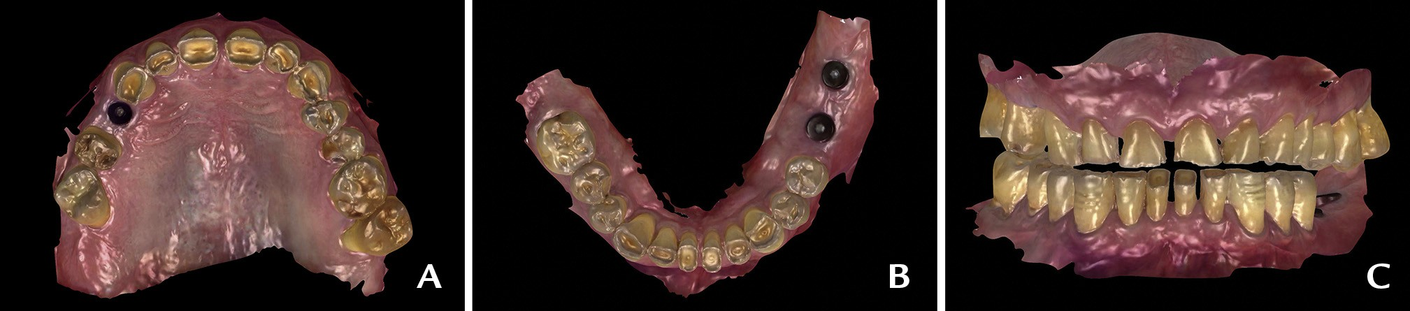
Figure 1. Digital preview of diagnostic intraoral scans with toggled STL views. A, Maxillary STL occlusal view (STL 1). B, Mandibular STL occlusal view (STL 2). C, Maxillomandibular relationship record at proposed intermaxillary treatment position. STL, standard tessellation language.
3. Place a polyvinyl siloxane (PVS) index (Hydrorise Putty; Zhermack SpA) over a Fox plane and position it parallel to the horizon in a frontal view and parallel to the Camper line in a profile view. Orient the plate properly in the frontal view by using a bubble-level device (Hot Shoe Level; ChromLivesDirect) placed over the Fox plane (Fig. 2A).
4. Once the PVS index has polymerized, transfer a vertical line corresponding to the facial midline and a horizontal line parallel to the Fox plane over the surface of the PVS index. Mark these 2 lines first and use them as a guide to make 2 incisions with a scalpel over the PVS index (Fig. 2B). If necessary, trim the PVS index to leave the second sextant clearly exposed to allow the intraoral scanner to capture the teeth and PVS index properly.
5. Duplicate the scan of the maxillary dentition (STL 1) and intraorally scan (STL 4) the maxillary arch with the PVS index in place starting from the exposed area of the teeth. This method ensures that STL 1 and 4 have the same XYZ spatial coordinates (Fig. 2C).
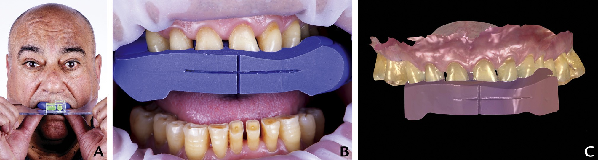
Figure 2. Maxillary position recording. A, Orient Fox plane by means of bubble level and adjust until plate horizontal to frontal view and parallel to Camper plane on profile view. B, Mark 2 perpendicular lines corresponding to facial midline and horizon and then perform 2 incisions. C, Maxillary arch scan with PVS index in place (STL 4). PVS, polyvinyl siloxane; STL, standard tessellation language.
6. Clinically verify and measure the incisal edge position based on esthetic and functional parameters.
7. Import the intraoral STL files into CAD software (exocad DentalCAD; exocad GmbH). Add STL 4 as “generic visualization mesh” (GVM) (a name given to a specific type of mesh that can be added in exocad expert mode platform that allows the user to view an imaginary plane that can be oriented in 3 different axes). Match STL 1 and STL 4 and rotate until the vertical and horizontal lines of STL4 coincide with the background grid lines (Fig. 3A).
8. Create a plane (GVM 1) (a name given to a specific type of a mesh that can be added in exocad expert mode platform that allows the user to view an imaginary plane that can be oriented in 3 different axes) and orient it parallel to the lower surface of the PVS index reference plane (Fig. 3B).
9. Create a second plane (GVM 2) parallel to the previous one and raise it until it touches the incisal edge of the planned maxillary central incisor. This plane represents the occlusal reference for the functional and esthetic rehabilitation (Fig. 3C).
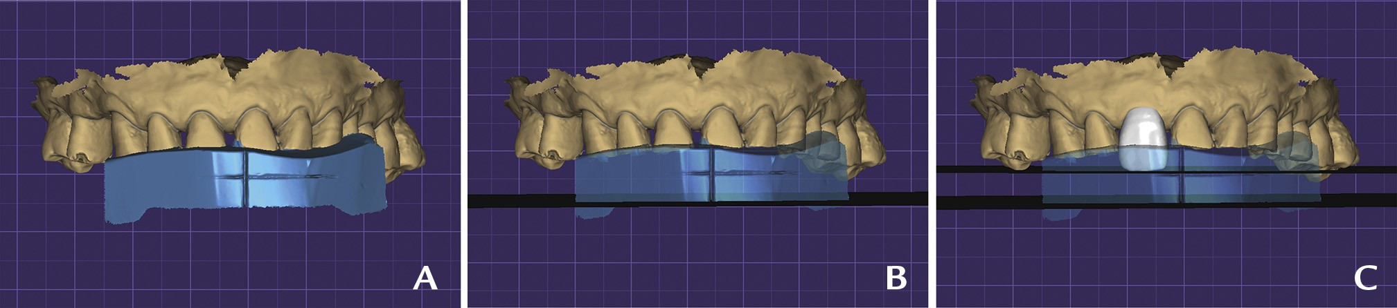
Figure 3. CAD step 1: Maxillary orientation. A, File matching of maxillary scan (STL1) and intraoral scan of PVS index reference (STL4). B, File matching of maxillary scan (STL1), intraoral scan of silicone reference (STL4), and plane generated parallel to bottom surface of PVS index (GVM 1). C, Maxillary right central incisor design based on clinical references and plane generated parallel to GVM 1 touching incisal edge of element (GVM 2). CAD, computeraided design; GVM, generic visualization mesh; PVS, polyvinyl siloxane; STL, standard tessellation language.
10. Run the articulator module in the expert mode of the CAD software program (exocad DentalCAD; exocad GmbH) and situate the proposed occlusal plane (GVM 2) correspondent with the Bonwill triangle in the exocad articulator by default. Make STL 4 visible to better position the cast in the virtual articulator (Fig. 4A, 4B).
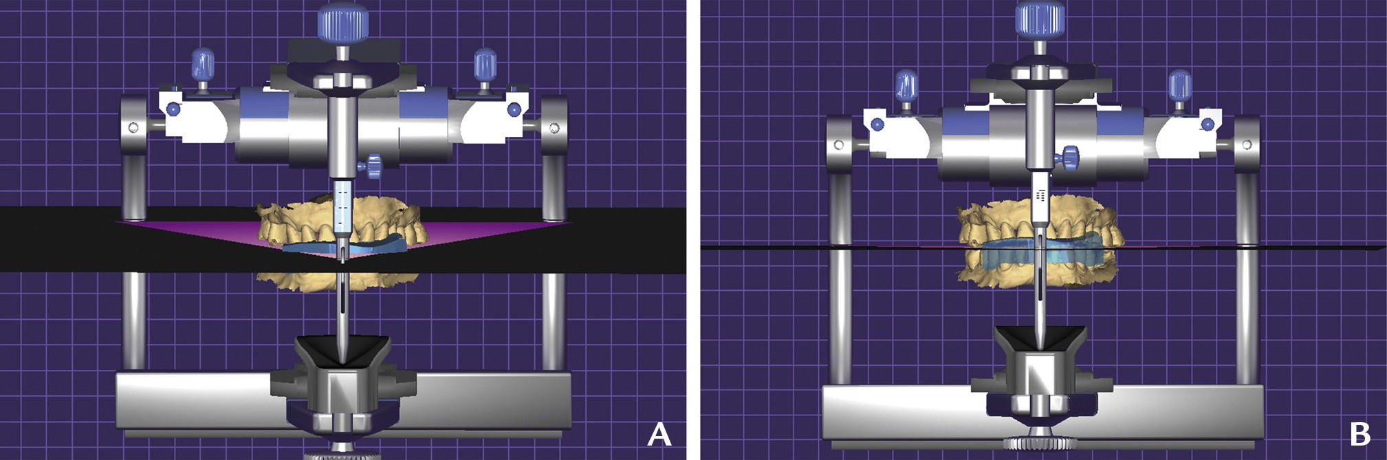
Figure 4. CAD step 2: Virtual articulator. Orientation of generated occlusal plane of reference (GVM2) coincident to Bonwill triangle A, Frontal inclination to view GVM2 and Bowell triangle coincident. B, CAD working frontal view perpendicular to occlusal plane. CAD, computer-aided design; GVM, generic visualization mesh.
11. Design complete mouth virtual diagnostic waxing by using GVM 2 (a name given to a specific type of mesh that can be added in Exocad expert mode platform that allows the user to view an imaginary plane that can be oriented in 3 different axes) as a reference plane (Figs. 5, 6). 3-dimensionally print the maxillary and mandibular models (XFAB 2000; DWS/Resin: Invicta 915; DWS) and fabricate a new PVS matrix (Hydrorise Putty; Zhermack SpA).
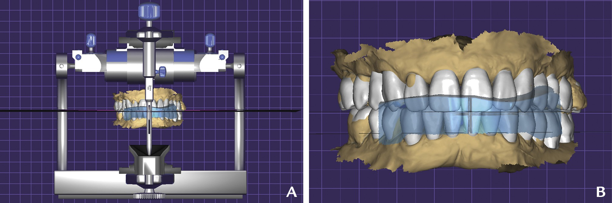
Figure 5. CAD step 3: Complete mouth diagnostic waxing. A, CAD frontal view perpendicular to occlusal plane. B, Frontal view of file matching complete mouth diagnostic waxing and PVS index reference scan (STL 4). CAD, computer-aided design; PVS, polyvinyl siloxane; STL, standard tessellation language.
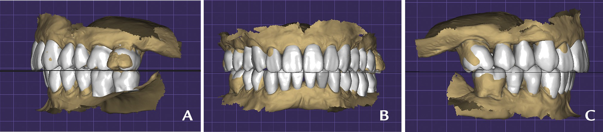
Figure 6. CAD step 3: Complete mouth diagnostic waxing. A, Right lateral view. B, Frontal view. C, Left lateral view.
12. Make a maxillary and mandibular treatment simulation with interim bisacrylic resin material (Protemp 4; 3M) and evaluate the esthetics and function (Figs. 7, 8).
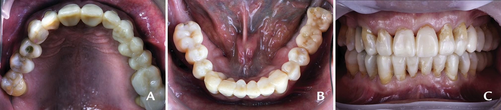
Figure 7. Trial restorations, intraoral view. A, Maxillary occlusal view. B, Mandibular occlusal view. C, Frontal view in centric occlusion.
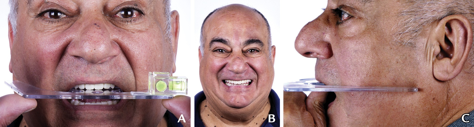
Figure 8. Extraoral images of treatment simulation. A, Frontal plane parallelism assessment by means of Fox plane and bubble level, frontal view. B, Maximum smile, frontal view. C, Camper plane parallelism assessment by means of Fox plane, left profile view.
DISCUSSION
Digital dentistry has paved the way for a more efficient dental workflow. The many tools that have been integrated into digital technology have made dental procedures more accurate and simpler.10 The use of maxillary orientation and occlusal plane records offers a key step to ensuring a functional and esthetic outcome in full-mouth rehabilitations.
A wide range of techniques have been adopted to position the maxillary in a 3-dimensional space and to record the occlusal plane.5,12 One way of orienting the maxillary model is by superimposing the CBCT-generated Digital Imaging and Communications in Medicine (DICOM) file over the maxillary intraoral scan STL file; another technique consists of using virtual reality to accurately mount the maxilla.6,9 However, one of the most frequent techniques entails using a CAD software platform to superimpose the extraoral frontal view image JPEG file (at maximum smile and with cheek retractors) over the intraoral upper maxilla scan STL file.13 This technique poses the challenge of photographing the patient in a completely natural head position. The natural head position is a standardized, reproducible position, with the head in an upright posture and eyes focused on a point in the distance at the eye level such that the visual axis is horizontal. To align 2 objects, the posterior and anterior points should be superimposed; because of the nature of frontally captured photographs, posterior teeth and distal surfaces are not represented adequately; therefore, the resultant alignment will not be accurately performed in the CAD phase. Many of the drawbacks mentioned in the latter technique can be overcome by using the present technique because it allows the patient’s head position to be accurately adjusted parallel to the horizon by using a Fox plane and a bubble level. This technique also omits the superimposition step in the CAD phase because the PVS index (representing the horizon frontally and Camper plane sagittally) is scanned on a copy of the original intraoral scan of the maxilla and has the same X, Y, Z orientation in the CAD software program.
SUMMARY
The maxillary orientation silicone key provides a method of virtually mounting the maxillary scan and transferring both the functional and the esthetic occlusal reference plane in a digital workflow. As digital technologies continue to advance, adjustments to the technique will be required.
REFERENCES
1. Davidowitz G, Kotick PG. The use of CAD/CAM in dentistry. Dent Clin North Am 2011;55:559-70.
2. Alghazzawi TF. Advancements in CAD/CAM technology: options for practical implementation. J Prosthodont Res 2016;60:72-84.
3. Van Noort R. The future of dental devices is digital. Dent Mater 2012;28:3-12.
4. Solaberrieta E, Garmendia A, Minguez R, Brizuela A, Pradies G. Virtualfacebow technique. J Prosthet Dent 2015;114:751-5.
5. Lepidi L, Chen Z, Ravida A, Lan T, Wang HL, Li J. A full-digital technique to mount a maxillary arch scan on a virtual articulator. J Prosthet Dent 2019;28:335-8.
6. Shetty S, Shenoy KK, Sabu A. Evaluation of accuracy of transfer of the maxillary occlusal cant of two articulators using two facebow/semi-adjustable articulator systems: an in vivo study. J Indian Prosthodont Soc 2016;16:248.
7. Pound E. Esthetic dentures and their phonetic values. J Prosthet Dent 1951;1:98-111.
8. Kalman L, Chrapka J, Joseph Y. Digitizing the facebow: a clinician/technician communication tool. Int J Prosthodont 2016;29:35-7.
9. Koralakunte PR, Aljanakh M. The role of virtual articulator in prosthetic and restorative dentistry. J Clin Diagn Res 2014;8:ZE25-Z28.
10. Ow RK, Djeng SK, Ho CK. Orientation of the plane of occlusion. J Prosthet Dent 1990;64:31-6.
11. Fradeani M, Barducci G. Esthetic rehabilitation in fixed prosthodontics. volume 1. Berlin: Quintessence Publishing Co Inc; 2008. p. 36-61.
12. Solaberrieta E, Otegi JR, Mínguez R, Etxaniz O. Improved digital transfer of the maxillary cast to a virtual articulator. J Prosthet Dent 2014;112:921-4.
13. Cervino G, Fiorillo L, Arzukanyan AV, Spagnuolo G, Cicciù M. Dental restorative digital workflow: digital smile design from aesthetic to function. Dent J (Basel) 2019;7:30.
14. Petre A, Drafta S, Stefanescu C, Oancea L. Virtual facebow technique using standardized background images. J Prosthet Dent 2019;121:724-8.
15. Pereira AL, De-Marchi LM, Scheibel PC, Ramos AL. Reproducibility of natural head position in profile photographs in children aged 8 to 12 years old, with and without an auxiliary cephalostat. Dental Press J Orthod 2010;15:65-73.