Merging Clear Aligner Therapy With Digital Smile Design to Maximize Esthetics and Minimize Tooth Reduction
Digital smile design (DSD) used in combination with an esthetic pre-evaluative temporary restoration is a reliable means of minimizing the removal of tooth structure when ceramic veneers are being placed. When patients present with poorly aligned teeth, the use of clear aligners may be considered to properly position the teeth based on the desired outcome. This article, which illustrates a method to systematically diagnose, plan, and stage treatment for a smile makeover, describes the merging of DSD with clear aligner therapy to enable clinicians to recognize digitally where to position the teeth using orthodontic movement. This approach allows the desired esthetic design to be attained while enabling minimal tooth reduction.
More about digital planning of orthodontic treatment you can find in our course "Kois principles for digital planning of prosthetic and orthodontic treatment" by Dr. Tak On Tse Ryan.
Ceramic veneers are highly esthetic restorations with predictable outcomes. They have excellent success rates when bonded to enamel. However, as the amount of tooth structure removed increases, typically the success rate of the restoration declines and the biomechanical risk rises. Digital smile design (DSD) protocols allow the clinician to plan the final position and shape of the teeth before any irreversible changes are made.
Combined with the use of an esthetic pre-evaluative temporary, DSD provides a highly reliable clinical process to minimize the removal of tooth structure when ceramic veneers are being placed.
Once the smile is designed using DSD, a preoperative temporary restoration is made and placed in the mouth. Esthetics, phonetics, and function are then evaluated, and when these are acceptable to the patient and clinician the teeth are prepared through the temporary material, preventing unnecessary removal of tooth structure. In situations where patients present with poorly positioned teeth, clear aligners (eg, Invisalign®, Align Technology, invisalign.com) may be used to properly position the teeth based on the desired end result, allowing for an esthetic outcome without significant removal of tooth structure. This article describes how to merge DSD with clear aligner therapy so that the clinician can know where to position the teeth using orthodontic movement, enabling tooth structure removal to be minimized while allowing the desired esthetic design to be achieved. Patients often are motivated to accept clear aligner treatment as a means of accomplishing their esthetic goals while maintaining tooth structure integrity.
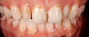 Fig 1. Preoperative close-up retracted view showing peg-shaped lateral incisors and cross-bite on tooth No. 26.
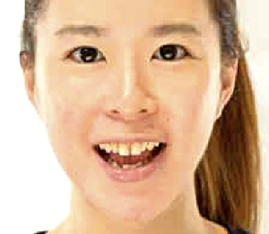 Fig 2. Preoperative view of the patient, who presented with concerns about an unattractive smile.
Clinical Case Overview
A 29-year-old woman presented for dental care, unhappy with the appearance of her smile. Intraoral examination revealed peg lateral incisors, teeth Nos. 7 and 10, with spaces between adjacent teeth; lower incisors angled to the patient’s right and crowded; and cross-bite at Nos. 7 and 26 due to No. 26 being positioned labially (Figure 1).
The patient’s medical history showed she was in good health with no contributory medical issues. Regarding the patient’s dental history, her only concern was the appearance of her smile.
Diagnosis and Risk Assessment
Periodontal: Radiographic evaluation revealed no attachment loss or bone loss. Bleeding on probing was evident on the lingual side of the lower anterior teeth. The patient was diagnosed as American Academy of Periodontology (AAP) 1.
Risk: Low
Prognosis: Good
Biomechanical: The patient had no caries and a few small composite restorations.
Risk: Low
Prognosis: Good
Functional: Despite anterior misalignment, with cross-bite on Nos. 7 and 26, the patient had acceptable function. There was no obvious attrition. The upper anterior teeth had mild crowding.
Risk: Low
Prognosis: Good
Dentofacial: When smiling, the patient fully revealed the upper gingival contours. The incisal edges of teeth Nos. 8 and 9 were well-positioned. However, the midline tilted to the left side, and these teeth had discoloration in the gingival one third.
Risk: High
Prognosis: Poor
Treatment Plan
The treatment plan was to modify the patient’s smile using veneers in a minimally invasive approach. The DSD and mock-up would be utilized to test-drive the treatment outcome. This would afford the patient the opportunity to not only give the smile a trial period but also to see the value of the aligner therapy before the veneer preparation. After the patient agreed to the clear aligner therapy, teeth Nos. 6 through 11 would be moved to the desired position and minimally prepared for the final veneers.
While alternative plans utilizing veneer treatment without clear aligner therapy were also presented to the patient, she chose the full treatment plan after being motivated by the mock-up and gaining an understanding of the treatment goal using the DSD.
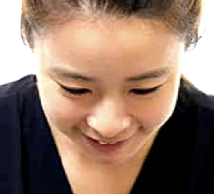 Fig 3. Preoperative 12 o’clock view.
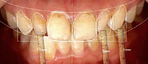 Fig 4. Photograph showing the proposed changes to the length of teeth Nos. 7 (lengthen 1 mm), 10 (lengthen 2 mm), and 11 (lengthen 1 mm).
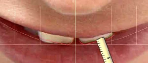 Fig 5. The 12 o’clock view photograph provided a visualization of the upper incisor positions. The central incisor edges would be moved labially 1 mm through the addition of the veneer, and the angulation of tooth No. 8 would be altered to follow the contour of the lip.
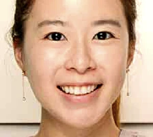 Fig 6. The motivational mock-up in place.
Phase 1: DSD and Motivational Mockup
The standard DSD protocol requires four extraoral photographs to be taken: retracted view (Figure 1), smile view (Figure 2), lateral view, and 12 o’clock view (Figure 3).13,14 The retracted and smile views are used to establish the dentofacial midline, proper incisal edge position, smile curve, and smile design. The 12 o’clock view provides a reference for the incisal edge position in relation to the wet-dry border of the lower lip. The lateral view (not shown) offers a reference for the incisor position and angulation.
Smile design begins by determining the upper incisal edge position, as proposed by Spear15 and Kois.16 Tooth size, tooth proportion, and gingival contours are then designed in sequential steps once a digital ruler is calibrated (Figure 4).
Next, the upper incisor position in relation to the patient’s lower lip is determined, using the lateral smile view and 12 o’clock view (Figure 5) photographs. In this case, after the DSD was completed, teeth Nos. 7 through 10 were planned for the addition of 1 mm labially and incisally. The technician fabricated the wax-up according to the DSD, and a silicone index was then fabricated for the mock-up. Temporization material (Protemp™, 3M ESPE, 3M.com) was injected into the silicone index and applied intraorally without any tooth preparation.
The patient was highly motivated by the mock-up and did not want it removed (Figure 6); however, she became aware that the esthetic lengthening on tooth No. 7 prevented her from closing her teeth together. This realization allowed the patient to understand the need to correct her cross-bite with the use of clear aligner therapy (Invisalign).
Phase 2: Merging the Software Treatment Plan With DSD
An intraoral scan (CEREC®, Dentsply Sirona, dentsplysirona.com) was taken and sent to an Invisalign facility. Instruction was given to the technician, and the ClinCheck® software (Align Technology) treatment plan model was prepared. Using Invisalign, the primary treatment objectives were to correct the anterior cross-bite, minimize removal of sound tooth structure, and create space bilaterally around the peg lateral incisors to accommodate ideal contour and angulation.
Currently, there is no software available to digitally combine DSD with Invisalign ClinCheck, so the images from each were superimposed using three reference lines marked on each photograph: the dental midline, a line between the highest points of the incisal surfaces of teeth Nos. 8 and 9, and a line between the cusp tips of teeth Nos. 6 and 11 (Figure 7 and Figure 8).13 The clinician then reoriented the software treatment plan to match these three lines and captured the view for Invisalign as a reference (Figure 9). This is a critical step because the technician must match the software model with the patient’s face.
The next step was to confirm the software model by superimposing the pretreatment ClinCheck photograph to the DSD photograph (Figure 10). If the former does not match the latter, the technician must reorient the software model; otherwise, the teeth will move to undesirable positions.
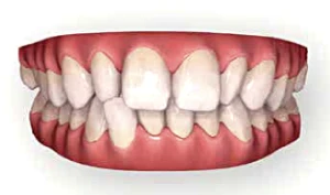 Fig 7. Screen shot of facial view of the preoperative ClinCheck software image.
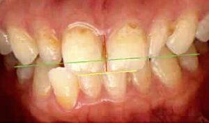 Fig 8. DSD photography with three reference lines: midline (red), middle of incisal plane of tooth No. 8 to middle of incisal plane of No. 9 (yellow), and tip of canine to tip of canine (green). The clinician can now orient the software treatment plan to match the position of the anterior teeth.
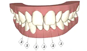 Fig 9. Screen shot of oriented software image after it was adapted to the DSD photographs.
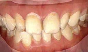 Fig 10. ClinCheck photograph superimposed with the DSD photograph to implement facially driven tooth movement.
Phase 3: Verify Software Model Result With DSD; Create Invisalign Plan
Once the ClinCheck photograph was matched with the DSD, the image of the predicted Invisalign result was then superimposed to the DSD photograph. This allowed the clinician to verify the ClinCheck result with the patient’s face (Figure 11 and Figure 12).
This merging procedure is necessary so that the tooth movement caused by Invisalign therapy may be facially driven. From the occlusal view, 0.5 mm space was planned on the mesial surfaces of teeth Nos.7 and 10, and 0.2 mm space was planned on the distal aspects. With more mesial than distal space available, the restorations would be able to create a visually pleasing mesial angulation to the lateral incisors (Figure 13), whereas if the spaces were greater distally, the lateral incisors would be angled distally, generating an unsightly result. Teeth Nos. 8 and 9 were retracted by 1 mm to achieve ideal tooth position that would allow the restorations to be placed with minimal tooth structure removal (Figure 14 through Figure 16).
Phase 4: Clear Aligner Treatment
Fourteen aligners were used to complete the Invisalign treatment in 8 weeks (Figure 17 and Figure 18). A photobiomodulation device (OrthoPulse®, Biolux Research, orthopulse.com) was utilized to accelerate movement of the teeth. The patient’s use of a dental monitoring application (Dental Monitoring, dental-monitoring.com) allowed tooth movement to be remotely monitored and aligners to be efficiently sequenced when movement was complete.
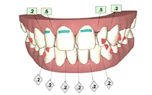 Fig 11. Screen shot of postoperative software image.
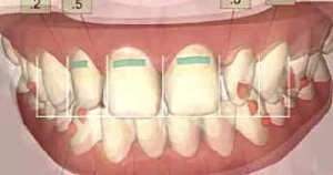 Fig 12. Post-treatment software image superimposed with golden proportional ruler and calibrated digital ruler. This image offers a general idea about tooth movement in the mouth, allowing the clinician to fore-see that the anticipated outcome will match the DSD planning. The image does not line up precisely with the image in Fig 10 in the posterior because it is 2-dimensional; however, this case concentrates only on the anterior. The aim is for effective communication with the lab. The clinician also could measure tooth position with CAD/CAM to verify the final position.
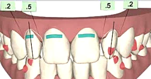 Fig 13. Representation of the final contours of teeth Nos. 7 and 10 in the software model with more mesial space than distal.
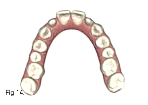 Fig 14. Occlusal view of the software model preoperatively.
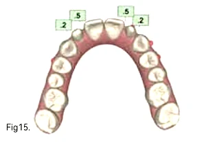 Fig 15. Occlusal view of post-orthodontic software model.
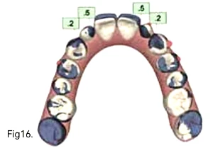 Fig 16. Occlusal view showing an overlay of the pre- and post-orthodontic software models, with the purple areas representing the tooth position in the preoperative model.
Phase 5: Final Restorations
New photographs were taken to update the DSD after completion of Invisalign treatment. Veneers were planned for teeth Nos. 7 through 10, and composite layering was planned as an additive strategy for tooth No. 6. The wax-up was fabricated and a “trial smile” was used to test-drive the new smile. The trial smile was also used as the esthetic pre-evaluative temporary and preparation guide for the final restorations.
The preparation margins were smoothed using an air scaler (SONICflex®, KaVo Dental, kavousa.com). Then, with the use of a two-cord retraction technique, the preparations were scanned with an intraoral scanner (CEREC), and acrylic temporaries (Protemp) were fabricated using a stent created from the wax-up. The veneers were milled with the aid of the CEREC biocopy function based on the wax-up.
The final restorations were created using e.max® HT ingot A1 shade (Ivoclar Vivadent, ivoclarvivadent.com) with ceramic layering. The veneers were cemented with a light-cured nanofilled composite resin (Filtek™ Supreme Ultra, shade CT, 3M ESPE). The composite was preheated in a composite warmer prior to cementation. The final restorations are shown in Figure 19 and Figure 20.
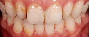 Fig 17. Close-up photograph after completion of clear aligner treatment.
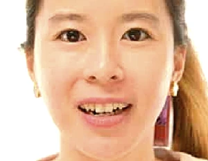 Fig 18. Full-face view after completion of clear aligner treatment.
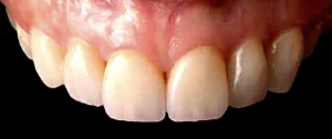 Fig 19. Postoperative close-up view of maxillary anterior teeth.
 Fig 20. Full-face view of the patients new smile.
Discussion
By merging clear aligner therapy with DSD, teeth can be “moved” digitally, providing directional control and quantification. For basic, non-complicated cases the three-line technique shown here is a simple and economical way to perform this merger. In the present case, symmetry and angulation of the peg laterals were able to be visualized in three dimensions, the cross-bite correction was planned and executed accurately, and minimal tooth structure was removed on the central incisors. As carefully as the DSD and Invisalign data were merged, margin for error still existed, which will be the case until the two technologies are truly integrated. The author looks forward to this in the future.
Conclusion
This case illustrated a method to systematically diagnose, plan, and stage treatment for a smile makeover. The use of DSD allowed the clinician to preoperatively plan various approaches to treatment and visualize the outcome of each. The merging of Invisalign and DSD enabled the clinician to move the teeth to ideal positions for veneer restorations and achieve the desired esthetic results using minimally invasive dentistry. The new veneers were in harmony with the face and lower lip, and the spaces were impeccably closed.
The additive approach used in this case minimized tooth preparation and also made the teeth more prominent in the patient’s smile. The patient was satisfied with not only the excellent esthetics but also the minimal removal of tooth structure.
References
Gürel G. The Science and Art of Porcelain Laminate Veneers. Chicago, IL: Quintessence Publishing; 2003.
Garber DA, Goldstein RE, Feinman RA. Porcelain Laminate Veneers. Chicago, IL: Quintessence Publishing; 1988.
Sadowsky SJ. An overview of treatment considerations for esthetic restorations: a review of the literature. J Prosthet Dent. 2006;96(6):433-442.
Dumfahrt H, Schäffer H. Porcelain laminate veneers. A retrospective evaluation after 1 to 10 years of service: part II—clinical results. Int J Prosthodont. 2000;13(1):9-18.
Fradeani M. Six-year follow-up with Empress veneers. Int J Periodontics Restorative Dent. 1998;18(3):216-225.
Fradeani M, Redemagni M, Corrado M. Porcelain laminate veneers: 6- to 12-year clinical evaluation—a retrospective study. Int J Periodontics Restorative Dent. 2005:25(1):9-17.
Burke FJ, Lucarotti PS. Ten-year outcome of porcelain veneers placed within the general dental services in England and Wales. J Dent. 2009; 37(1):31-38.
Beier US, Kapferer I, Burtscher D, Dumfahrt H. Clinical performance of porcelain laminate veneers for up to 20 years. Int J Prosthodont. 2012;25(1):79-85.
Tak OT, Kois JC. Digital Smile Design meets the dento-facial analyzer: optimizing esthetics while preserving tooth structure. Compend Contin Educ Dent. 2016;37(1):46-50.
Gürel G. Predictable, precise, and repeatable tooth preparation for porcelain laminate veneers. Pract Proced Aesthet Dent. 2003;15(1):17-24.
Magne P, Belser UC. Novel porcelain laminate preparation approach driven by diagnostic mock-up. J Esthet Restor Dent. 2004;16(1):7-16.
Gürel G, Morimoto S, Calamita MA, et al. Clinical performance of porcelain laminate veneers: outcomes of the aesthetic pre-evaluative temporary (APT) technique. Int J Periodontics Restorative Dent. 2012;32(6):625-635.
Coachman C, Calamita MA. Digital smile design: a tool for treatment planning and communication in esthetic dentistry. Quintessence Dent Technol. 2012;35:103-111.
Coachman C, Van Dooren E, Gürel G, et al. Smile design: from digital treatment planning to clinical reality. In: Cohen M, ed. Interdisciplinary Treatment Planning. Vol II: Comprehensive Case Studies. Chicago, IL: Quintessence Publishing; 2012:119-174.
Spear F. The maxillary central incisor edge: a key to esthetic and functional treatment planning. Compend Contin Educ Dent. 1999;20(6):512-516.
Kois JC. Diagnostically driven interdisciplinary treatment planning. Seattle Study Club J. 2002;6(4):28-34.
Ojima K, Dan C, Kumagai Y, Schupp W. Invisalign treatment accelerated by photobiomodulation. J Clin Orthod. 2016;50(5):309-317.
Dickerson T. Invisalign with photobiomodulation: optimizing tooth movement and treatment efficacy with a novel self-assessment algorithm. J Clin Orthod. 2017;51(3):157-165.
