en
Fabrication of a facially generated tooth reduction guide for minimally invasive preparations: A dental technique
/social-network-service/media/default/100783/8ac6d19f.jpg)
31
15 min read
27 April 2023
ABSTRACT
This article describes a 3D virtual diagnostic analysis for treatment planning an esthetically driven functional rehabilitation by using computer-aided design and computer-aided manufacturing (CAD-CAM) technology. In this protocol, a digitally planned diagnostic waxing (exocad DentalCAD) was used to visualize the proposed tooth position and the presence of areas without sufficient material thickness for the prospective additive restorations. This approach uses an additively manufactured clear resin guide to selectively reduce surfaces of a tooth erupted beyond the proposed occlusal plane. By using a 3D-printed occlusal reduction guide, the digital diagnostic waxing is accurately represented, tooth reduction controlled, and adequate occlusal clearance for the required restorative material thickness provided with a minimally invasive approach. (J Prosthet Dent 2021)
There are additional resources available to enhance your understanding of the digital dentistry you can find on our website.
Facial scanning technology, intraoral scanners (IOSs), and computer-aided design and computer-aided manufacturing (CAD-CAM) software programs provide a completely digital workflow that aids in the complete diagnostic analysis of the digitized patient.
The process is composed of data acquisition, data processing, data construction, and the clinical application of constructed data. Optical scans digitize the initial condition into a digital file in standard tessellation language (STL) format, which is then imported into an open or closed source dental CAD software program for diagnostic analysis. Ultimately, CAM technology produces the designed files by subtractive or additive manufacturing (AM).
Despite the advocacy of minimally invasive prosthodontics, determining how much tooth structure to remove remains challenging during tooth preparation. In additive treatments, the rehabilitation is guided by a definitive 3D volume (trial restoration) requiring no tooth preparation or minimal recontouring of damaged tooth structure. When tooth removal is necessary, the trial restorations are not fully indicative of the necessary preparation unless the teeth have been previously prepared. Even though tooth preparation guides have been described,16 improvements can be made by using digital technology.
This technique article describes a complete-arch AM clear resin template to guide the anterior or posterior areas of a tooth requiring reduction simultaneously. A digital workflow using facial photography, IOS, and CAD-CAM technology is described. The steps involved in this workflow explains how to virtually diagnose and fabricate the AM guide.
TECHNIQUE
With an IOS (TRIOS 3; 3Shape A/S), make scans to obtain the STL data of the maxillary dentition (STL 1) and mandibular dentition (STL 2) (Fig. 1A, 1B).
Make an intermaxillary registration scan (STL 3) in maximum intercuspation position (MIP) or centric relation (CR) depending on the required treatment position (Fig. 1C).
Import an extraoral frontal photograph (2 views: smile and retracted lip view) and intraoral STL files into a CAD software program (exocad DentalCAD; exocad GmbH) and orient the maxillary arch with the photograph (Fig. 2). Exercise caution in accurately superimposing the extraoral photograph and the scanned maxilla, as this is a crucial step in the correct application of the technique.
Make a diagnostic virtual waxing of the labial surfaces of the maxillary anterior teeth at the established jaw relationship (Fig. 3A). Export the waxed cast to a 3D printer (XFAB 2000; DWS) to print the waxed cast from cast resin (3D printable resin Invicta 915; DWS) and fabricate a polyvinyl siloxane guide (Hydrorise Putty; Zhermack) for the trial restoration appointment (Fig. 3B).
Make the trial restorations from an interim bisacrylic resin material (Protemp 4; 3M) and evaluate anterior esthetics and function. Make intraoral adjustments if necessary, and, if so, make new intraoral maxillary (STL 4) and mandibular (STL 5) scans (Fig. 3C).
Fabricate a polyvinyl siloxane guide (Hydrorise Putty; Zhermack) over a Fox plane (White Fox Plane; House Brand) and position it parallel to the Campers line. Once the silicone polymerizes, perform an intraoral scan (STL 6) with the silicone guide in place (Fig. 4 A, 4B).
Import STL 6 into a CAD software program (exocad DentalCAD; exocad GmbH) and superimpose it on STL 1 (Fig. 4C).
Generate a plane parallel to STL 6 that contacts the maxillary central incisor waxing to generate a posterior reference occlusal plane (STL 7) (Fig. 5A). Design complete-mouth, virtual wax patterns by using the occlusal plane in STL 7 as a reference (Fig. 5B).
Place margins extending beyond the established occlusal plane to generate “inlays” on each area of the tooth surface and then use the extrusion tool to extrude these inlays (Figs. 6, 7).
Design a 1.5-mm-thick structure covering the entire dentition with margins placed on the height of contour and calibrate the offset distance at 0.05 mm. Virtually subtract the “inlays” meshwork as negative attachments. A differential meshwork will identify the tooth areas to be reduced as windows. The windows help during tooth reduction by facilitating placement of the rotary instrument while smoothing the prepared tooth surface. The guide can sometimes be designed in 2 sections (such as in the mandibular arch) to prevent the software program from increasing the offset distance as it attempts to block undercuts between divergent teeth (Fig. 7C).
Save the STL files of the guide design and export them to a 3D printer (XFAB 2000; DWS) to print from clear biocompatible resin (3D printable resin DS5000; DWS) (Fig. 8A).
Immerse the 3D-printed guide in an ultrasonic alcohol bath (96%) for 15 minutes and proceed to continue the polymerization in an ultraviolet polymerization chamber (XYZ) for 10 minutes at C (Fig. 8A).
Disinfect the guides by immersion in a 2% chlorhexidine solution for 15 minutes.
Place the 3D-printed guide in the arch to be treated and verify fit. Proceed to prepare the teeth through the windows in the guide and follow the same protocol for all the areas requiring preparation (Fig. 8).
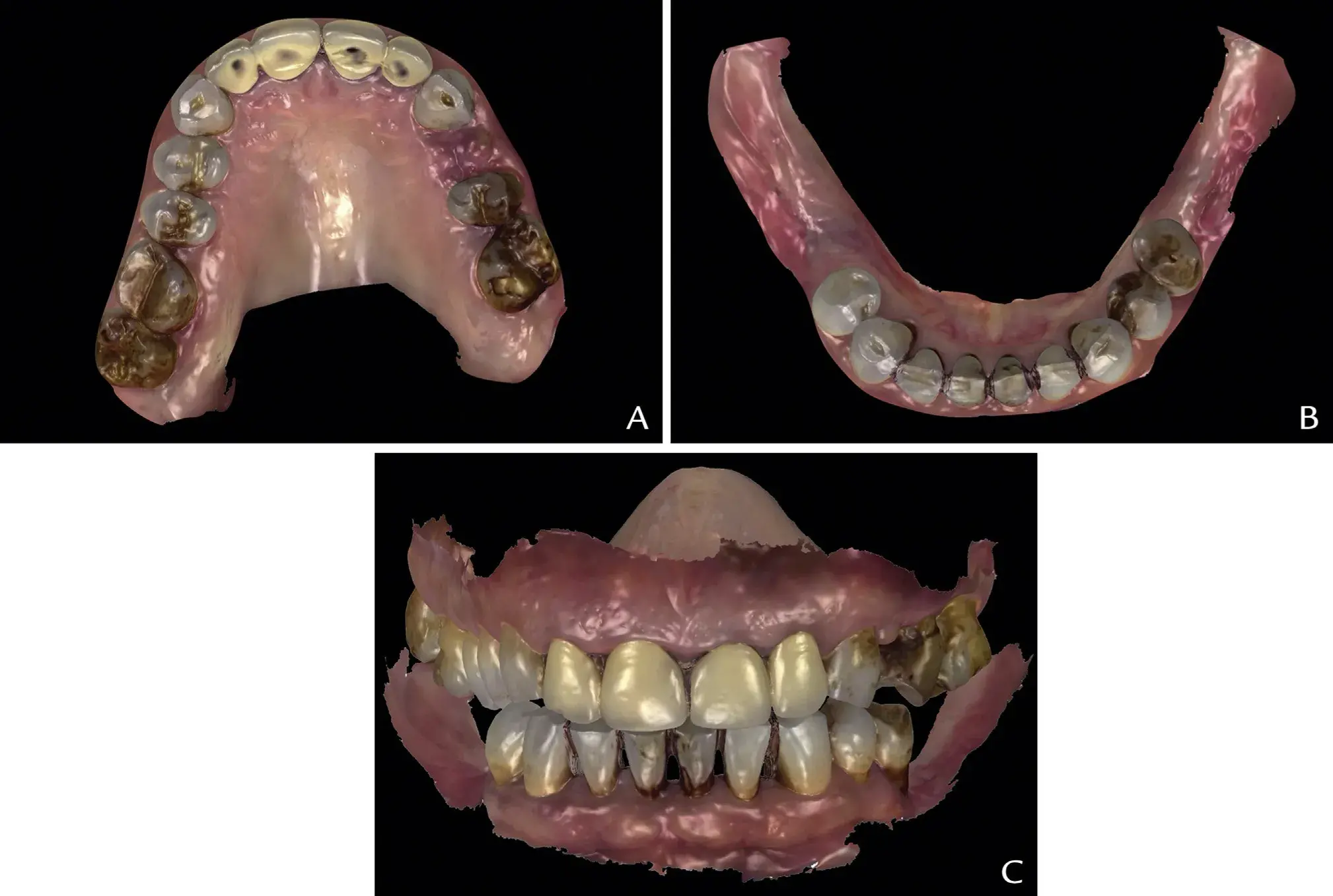 Figure 1. Digital preview of diagnostic intraoral scans with toggled STL views. A, Maxillary STL occlusal view (STL 1). B, Mandibular STL occlusal view (STL 2). C, Aligned STLs in treatment position at proposed intermaxillary treatment position (STL 3). STL, standard tessellation language.
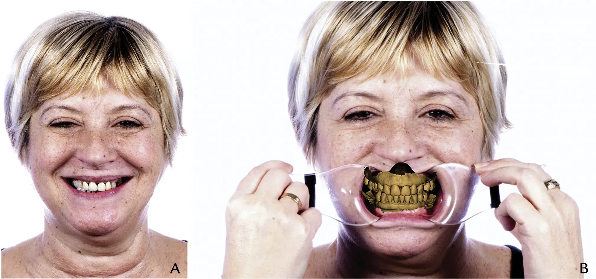 Figure 2. Facially driven smile design: Extraoral photographs. A, Maximum smile, frontal view. B, CAD superposition extraoral frontal picture with lip retractors and STL 3. CAD, computer-aided design; STL, standard tessellation language.
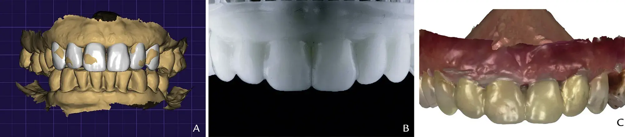 Figure 3. CAD phase 1: Virtual waxing. A, Diagnostic virtual waxing of maxillary anterior teeth. B, Three-dimensionally printed model of maxillary anterior waxing. C, Frontal view intraoral trial restorations from interim bis-acrylic resin material (Protemp 4; 3M) (STL 4). CAD, computer-aided design; STL, standard tessellation language.
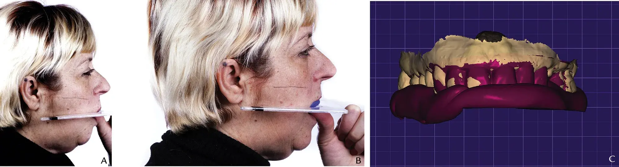 Figure 4. Occlusal plane recording. A, Preoperative situation: occlusal plane discrepancy assessment by means of Fox plane (White Fox Plane; House Brand), right profile view. B, Polyvinyl siloxane guide over Fox plane oriented parallel to Camper line, right profile view. C, CAD superposition of STL 1 and occlusal reference polyvinyl siloxane key intraorally scanned (STL 6). CAD, computer-aided design; STL, standard tessellation language.
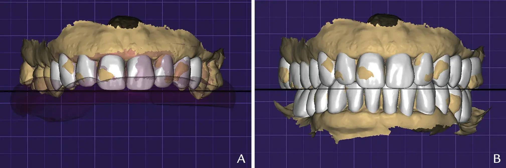 Figure 5. CAD phase 2: Complete-mouth, virtual waxing. A, Generation of plane (STL 7) parallel to base of occlusal reference polyvinyl siloxane key (STL 6), touching maxillary central incisors. B, Complete maxillary and mandibular virtual waxing. CAD, computer-aided design; STL, standard tessellation language.
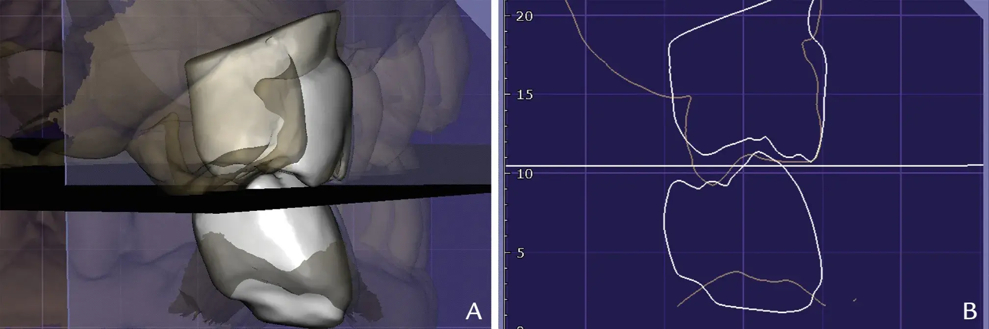 Figure 6. Visual assessment of preoperative supra-erupted tooth areas (right maxillary first molar in orange outline) and waxed teeth (right maxillary first molar and right mandibular first molar in gray outline), with generated occlusal reference plane STL 7. A, Three-dimensional view. B, Two-dimensional cut view. STL, standard tessellation language.
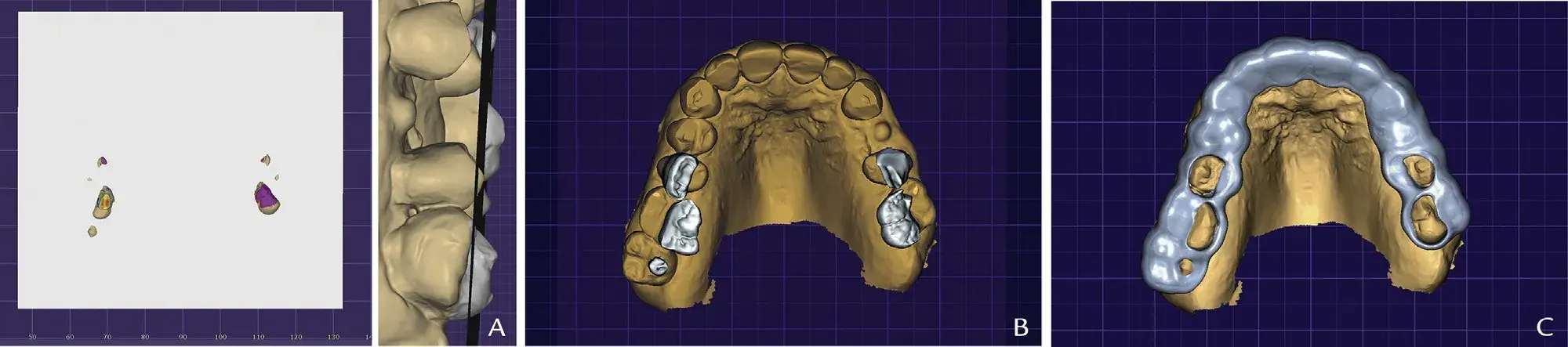 Figure 7. CAD phase 3: preview tooth areas extruding plane and generating clear resin reduction guide. A, Occlusal reference plane (STL 7) with supraerupted parts of maxillary preoperative STL file (STL 1), occlusal view. B, Inlays 1.5 mm in thickness with margins placed over areas of maxillary tooth (STL 1) extruding generated occlusal plane (STL 7), occlusal view. C, Selective reduction occlusal guide design, developed by Boolean difference between complete-coverage occlusal reduction guide and inlays (Fig. 5B), occlusal view. CAD, computer-aided design; STL, standard tessellation language.
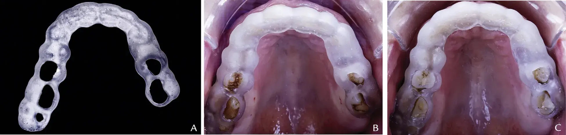 Figure 8. A, Three-dimensionally printed selective occlusal reduction guide, extraoral view. B, Preoperative 3D-printed selective occlusal reduction guide, maxillary occlusal view. C, Postoperative 3D-printed selective occlusal reduction guide, maxillary occlusal view.
You have the opportunity to gather more in-depth information about digital technologies in dentistry in our author's course "Digitalize the Dental Сlinic: A Complete Guide to Designing and 3D Printing" by Dr. August de Oliveira.
DISCUSSION
Minimal invasive treatments can be delivered by ensuring adequate tooth preparation to provide the minimum thickness for the restorative material. The presented digital workflow controls the amount of tooth tissue to be reduced and previews the space for the definitive restoration. Current CAD-CAM technology can simulate mandibular movements by using virtual articulators that can receive numerical values for the Bennett angle,
Bennett movement, vertical dimension, and horizontal condylar inclination. However, a major challenge in adopting the digital workflow has been to correctly orient the maxillary arch without the use of an analog facebow because digital casts are not properly oriented in the x, y, and z axes when they are digitized, which makes it difficult to transfer the occlusal plane.17 In the present technique, maxillary arch orientation is key to applying it by using appropriate points of reference to superimpose a 2D extraoral photograph file and a 3D scanned maxilla file. The occlusal plane orientation was generated by digitalizing the maxillary occlusal registration, made with the Fox plane.
The use of a dentofacial analyzer (DFA) has been described to digitalize the facial mid-line and occlusal plane orientation. Other techniques have included cone beam computed tomography (CBCT) scans, although these increase radiation exposure and are time-consuming, and complex 3D facial scanners. Inexpensive 3D facial scanners cannot generate high-quality meshes to align to dental casts, and reference markers are needed in the facial scan to align files, which makes it more difficult than using the Fox plane. More sophisticated software programs (such as from Zirkonzahn GmbH: Face Hunter, Plane Finder, and Plane System) represent a straightforward and precise solution.
An AM clear resin index provides an excellent fit, a clear visualization of the area to be prepared, and optimal access for the rotary instruments, minimizing the risk of excessive tooth preparation.19 Another advantage of the technique is control of the design of the selective reduction guide by using the tool “cut view,” which allows previsualization of the sagittal intersection areas among the baseline cast (STL1), the waxing, and the posterior reference occlusal plane. AM guide materials are susceptible to wear during tooth preparation from the rotary instruments. During the CAD phase, it is recommended to smooth the inner area of the windows according to the path of action of the rotary instrument and to use clear biocompatible colored resins for the 3D printing so that debris during the preparation can be seen and index wear noted.
SUMMARY
The AM guide described direct clinicians in selective tooth reduction by using a virtual diagnostic analysis, thus preserving natural tooth structure and providing sufficient thickness for the restorative material.
REFERENCES
Alghazzawi TF. Advancements in CAD/CAM technology: Options for practical implementation. J Prosthodont Res 2016;60:72-84.
Stanley M, Gomes Paz A, Miguel I, Coachman C. Fully digital workflow, integrating dental scan, smile design and CAD-CAM: case report. BMC Oral Health 2018;18:134.
Revilla-León M, Sánchez-Rubio JL, Besné-Torre A, Özcan M. A report on a diagnostic digital workflow for esthetic dental rehabilitation using additive manufacturing technologies. Int J Esthet Dent 2018;13:184-96.
Mangano F, Shibli JA, Fortin T. Digital dentistry: new materials and techniques. Int J Dent 2016;52:612-47.
Solaberrieta E, Otegi JR, Mínguez R, Etxaniz O. Improved digital transfer of the maxillary cast to a virtual articulator. J Prosthet Dent 2014;112:921-4.
Joda T, Ferrari M, Gallucci GO, Wittneben JG, Brägger U. Digital technology in fixed implant prosthodontics. Periodontol 2000 2017;73:178-92.
Shim JS, Kim JE, Jeong SH, Choi YJ, Ryu JJ. Printing accuracy, mechanical properties, surface characteristics, and microbial adhesion of 3D-Printed resins with various printing orientations. J Prosthet Dent 2020;124: 468-75.
Edelhoff D, Sorensen JA. Tooth structure removal associated with various preparation designs for anterior teeth. J Prosthet Dent 2002;87:503-9.
Schlichting LH, Resende TH, Reis KR, Magne P. Simplified treatment of severe dental erosion with ultrathin CAD-CAM composite occlusal veneers and anterior bilaminar veneers. J Prosthet Dent 2015;116:574-9.
Ammannato R, Ferraris F, Marchesi G. The “index technique” in worn dentition: a new and conservative approach. Int J Esthet Dent 2015;10:68-99.
Shillingburg HT, Sather DA, Wilson EL, Cain JR, Mitchell DL, Blanco LJ, et al. Fundamentals of fixed prosthodontics. 4th edition. Chicago: Quintessence Publishing Inc Co; 2012. p. 163-8.
Goodacre CJ, Campagni WV, Aquilino SA. Tooth preparations for complete crowns: an art form based on scientific principles. J Prosthet Dent 2001;85: 363-76.
Magne P, Belser UC. Novel porcelain laminate preparation approach driven by a diagnostic mock-up. J Esthet Restor Dent 2004;16:7-16.
Vailati F, Belser UC. Full-mouth adhesive rehabilitation of a severely eroded dentition: the three-step technique. Part 1. Eur J Esthet Dent 2008;3:30-44.
Gürel G. The science and art of porcelain laminate veneers. London: Quintessence; 2003. p. 145-9.
Cho SH, Nagy WW. Customized occlusal reduction guide made from a thermoplastic sheet. J Prosthet Dent 2015;114:307-8.
Brenes C, Babb C, Jurgutis L. Digital face-bow transfer technique using the dentofacial analyzer for dental esthetics and 2-D, 3-D smile design: a clinical report. J Oral Science and Rehab 2018;4:22-30.
Lin WS, Harris BT, Phasuk K, Llop DR, Morton D. Integrating a facial scan, virtual smile design, and 3D virtual patient for treatment with CAD-CAM ceramic veneers: A clinical report. J Prosthet Dent 2018;119: 200-5.
Wisithphrom K, Murray PE, About I, Windsor LJ. Interactions between cavity preparation and restoration events and their effects on pulp vitality. Int J Periodontics Restorative Dent 2006;26:596-605.
Lucas Caponi, DDS
Fady Raslan, DDS, CAGS
Miguel Roig, MD, DMD, PhD