
Functional Diagnostics of the ANS: Errors and Their Solutions
Machine translation
Original article is written in RU language (link to read it) .
We have always had a heightened interest in working with individual parameters of the lower jaw articulation. If you think about it, what do the trajectories of movements of the lower jaw represent? They are the result of not only the temporomandibular joints (heads of the lower jaw and menisci) but also the muscular system, ligaments, and dental arches.
About the diagnostics of internal disorders of the TMJ using MRI at the webinar Diagnostic Algorithms of MRI TMJ.
By conducting orthodontic, orthopedic, and therapeutic treatment, the doctor changes and creates new parameters for the articulation of the lower jaw or tries to preserve the old ones. How functional the new conditions will be for the operation of the above-described complex of anatomical structures will be shown over time. In this article, we would like to talk about the main stages that are an integral part of the initial functional diagnostics of the TMJ, and about the equipment necessary for diagnostics.
Conditionally, a doctor's work using additional equipment can be divided into work in real and virtual spaces. The single criterion for a successful outcome in these two formats is the correct use of equipment, understanding its technical capabilities, and the accuracy of its programming.
Stage I: Transferring the position of the upper/lower jaws to the articulator using average anatomical facebows, possible problems and their solutions
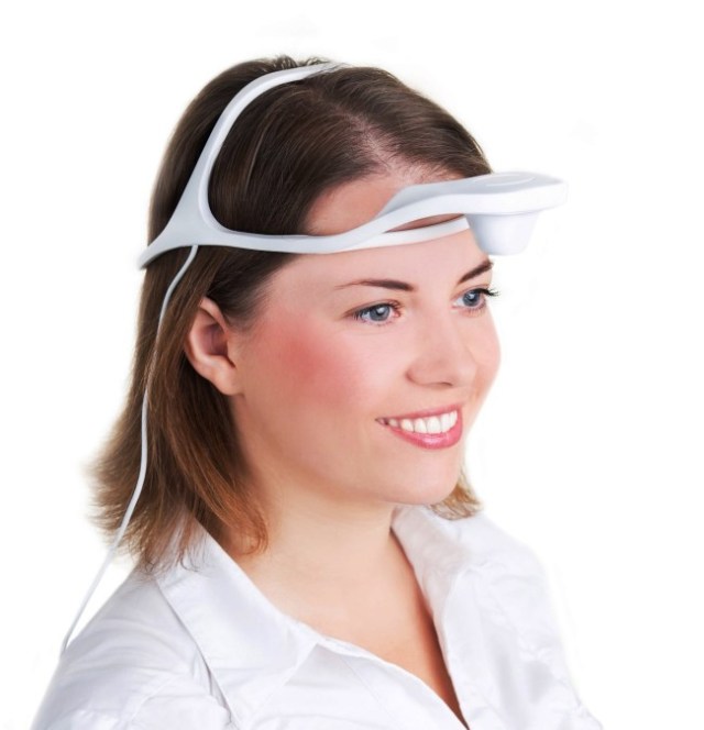
Average anatomical and anatomical facebows are used to transfer the plaster model of the upper/lower jaws to the articulator. How correctly the facebow is positioned on the patient's head affects subsequent diagnostics and treatment outcomes. There are two types of average anatomical facebows: those oriented on the patient's head according to skin landmarks relative to the Camper's or Frankfurt plane (figure 1).
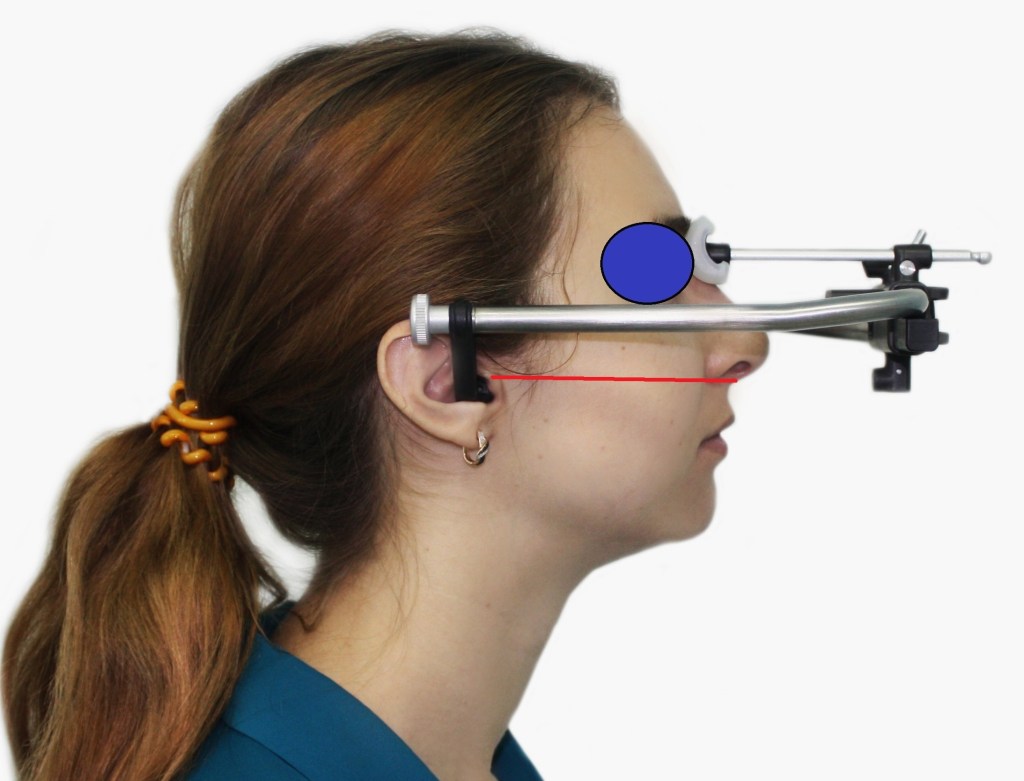
Figure 1. Location of the facial arc Arcus (Kavo).
Not in all clinical cases do the skin landmarks coincide with the bone landmarks, which can lead to errors in plaster casting of the model later on. The principle of working with such an arc is the mandatory maintenance of parallelism between the facial arc positioned on the patient's head and the Camper's plane, formed by the skin landmarks.
What to do if the skin landmarks do not coincide with the bone landmarks?
Conduct radiological examination of the head with radiopaque skin points above the described plane for more detailed analysis. Clinically, such a technique becomes complex, and not all clinics can perform such a radiological examination. Neglecting this parameter can lead to a change in the tilt of the model in the sagittal plane (figure 2).
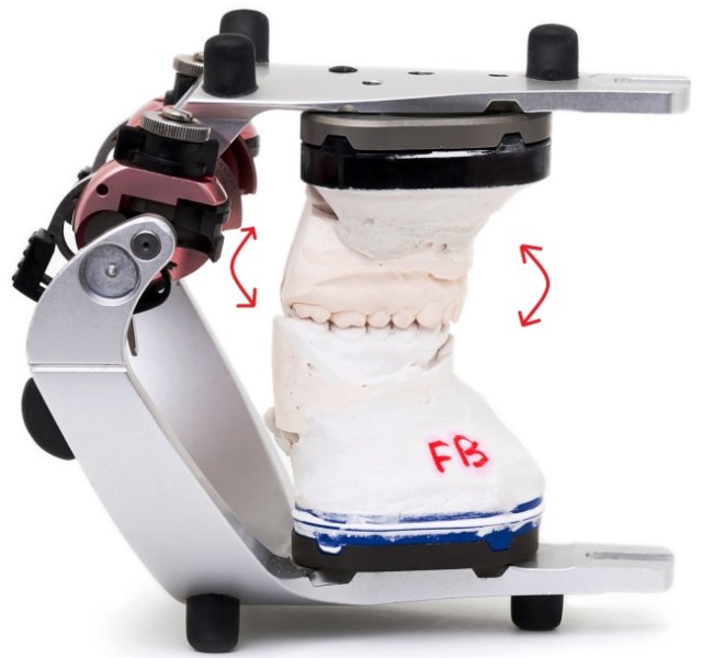
Figure 2. Rotation of the model in the sagittal projection clockwise or counterclockwise.
What to do if the Camper's plane is not parallel to the prosthetic plane?
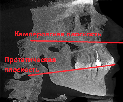
Figure 3. CT of the head. Analysis of plane orientations.
And why should the planes be parallel (Figure 3)? If in the articulator the upper jaw model is elevated in the incisor region in the sagittal projection, but the facial arch is correctly oriented relative to the bony landmarks of Camper's plane, this will not be considered an error.
Mistakes that occur when using average anatomical facial arches can arise in the sagittal projection (tilting the upper jaw model forward or backward), in the frontal plane (tilting the upper jaw model to the right or left), and in the horizontal plane (rotation of the model, Figure 4).
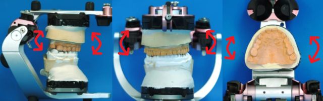
Figure 4. Possible movements of the model in/out of the articulator.
One of the most serious errors is the inability to control the distance from in/out to the joint heads (figure 5).
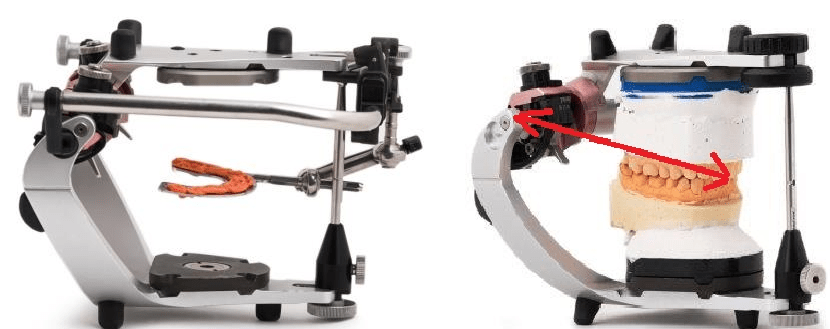
Figure 5. Plastering the model in/out of the articulator using a face bow. Lack of control over the relationship between the model and the articulator's joint mechanisms.
This error is related to the fact that there is no reference point for the incisors on the occlusal fork with the recorder, therefore the distance from the model to the joints is not fixed. It is known that for the normal functioning of plaster models in the articulator, taking into account average parameters, the data of the Bonwill triangle (distance from the lower incisors to the joint mechanisms of the articulator) must be considered. However, since the use of a facebow implies the transfer of the upper model, it is primarily necessary to maintain the individual distance from the upper incisors to the joint mechanisms.
Thus, when using average anatomical facebows, there are inaccuracies that may or may not be correctable. This is due to flaws in the design of the bows themselves.
Solutions to problems arising from the use of average anatomical facebows
To solve the problems arising from the use of average anatomical facebows, we have developed a technique for transferring the upper model into the articulator and additional equipment – a central marker and stand (figure 6).
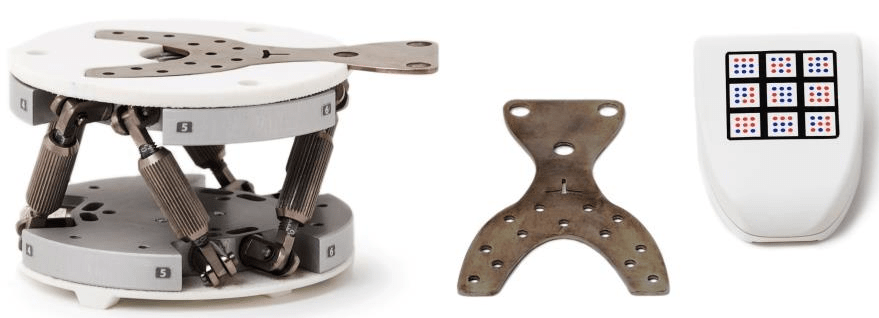
Figure 6. Stand for plastering and central marker (Prosystom).
The central marker consists of a fork and a controller. There is a mark for chisels on the marker to control the placement of the model. By using the central marker, we have eliminated any skin landmarks to minimize errors (Figure 7).
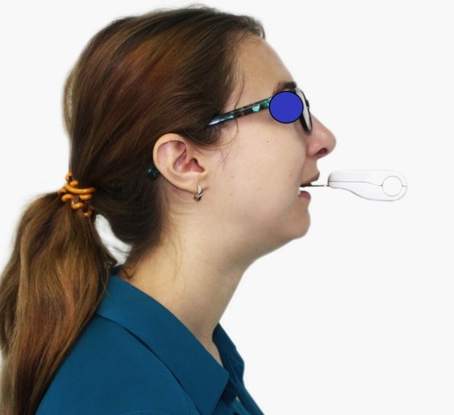
Figure 7. Positioning of the central marker during registration of the prosthetic plane.
After determining the individual position of the prosthetic plane, the controller outputs data for setting the stand according to individual parameters (Figure 8).
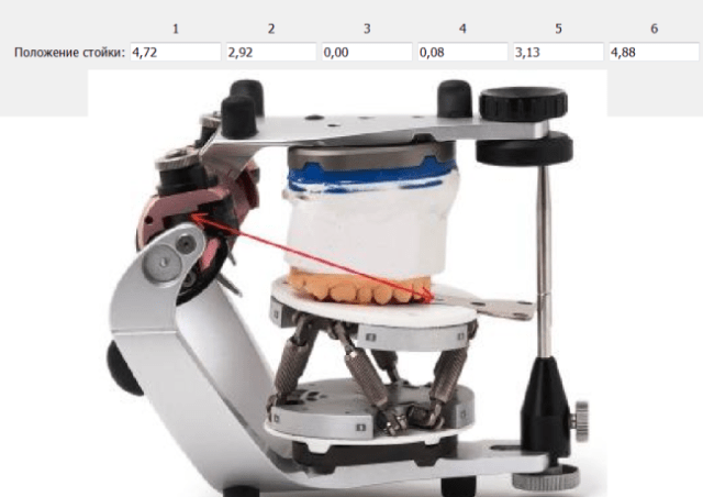
Figure 8. Plastering the model using the stand in the Protar articulator.
To take into account all individual parameters during plastering, we use an additional CT module (Figure 9).
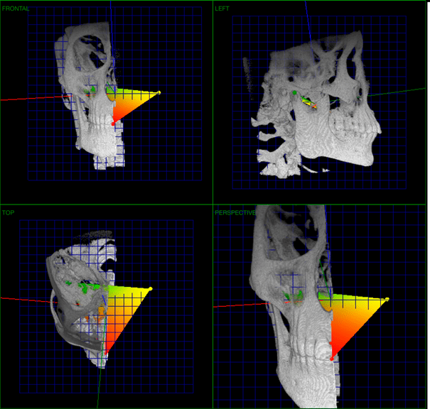
Figure 9. CT module for plastering (Prosystom).
This module allows measuring the individual distance from the incisors of the upper jaw to the joint heads for subsequent transfer to the articulator. This technique uses 3 landmarks: the inter-incisal point in the area of the cutting edge of the central teeth of the upper jaw and points in the area of the joint heads. Note: it is unjustified to set the hinge axis landmark using only CT, this is dictated by serious differences in the structure of the joint heads of a human and an articulator (figure 10).
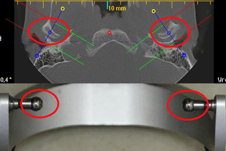
Figure 10. Comparative analysis of the anatomy of human joint heads and the joint heads of the lower frame of the articulator.
Therefore, we place the point in the joint area at the top of the joints. Defining a point on the joint mechanisms of the articulator also does not pose any difficulty. After the models are correctly plastered in the articulator taking into account individual parameters, you can proceed to its adjustment.
Stage II: Programming the articulator according to individual parameters, using electronic systems for recording articulation, errors occurring when using electronic axiographs
The second part of the article is dedicated to programming articulators: we will reveal some unresolved issues when using electronic axiographs, as these systems are the most accurate. The question regarding the high cost of electronic axiographs remains open. This equipment is secondary in operation and is only needed for recording the trajectories of movements and their digital values. Electronic registration systems have been on the market for a long time, but they are still not particularly in demand. Why? High price, lack of accessible information for doctors, errors in their use in complex clinical cases, some devices have a rather complex structure.
Electronic recording systems, when used correctly, are the only equipment that allows:
- to register any movement trajectories of the jaw;
- to obtain individual data for programming articulators;
- to obtain a three-dimensional representation of jaw articulation;
- to work in a virtual space with individual parameters;
- to obtain data for analyzing dynamic occlusion using virtual models;
- the use of these devices allows for dynamic monitoring of patients during long-term treatment.
Mechanical, electronic, and virtual articulators are the main equipment in this list, as they are used to manufacture constructions. Axioagraphs, on the other hand, are auxiliary equipment necessary for adjusting articulators.
The most common electronic systems are ultrasonic. These systems have their weaknesses.
Structure of a paraocclusal fork for fixing an ultrasonic sensor (figure 11).
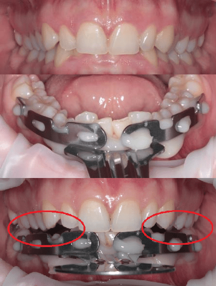
Figure 11. Placement of the paraocclusal fork on the dental arch l/l.
Deep incisal overlap serves as a relative contraindication for accurate articulation registration l/l. Also, with a low clinical crown height of the teeth l/l, and pathological wear of the frontal group of teeth l/l, the fork may hinder the usual occlusion of the dental arches. We consider this a serious drawback, especially in diagnosing patients with TMJ dysfunctions, as it leads to separation of the dental arches: contact remains mainly between the incisors u/u and the paraocclusal fork, which in turn can lead to uncontrolled displacement of l/l.
In such cases, it is possible to register the movement trajectories of l/l, but it will be practically impossible to determine where the joints were at the beginning of the trajectories (figure 12). Articulation analysis to obtain digital data for programming the articulator according to individual parameters will be meaningless, as the classical trajectories involving the dental arches will be altered.
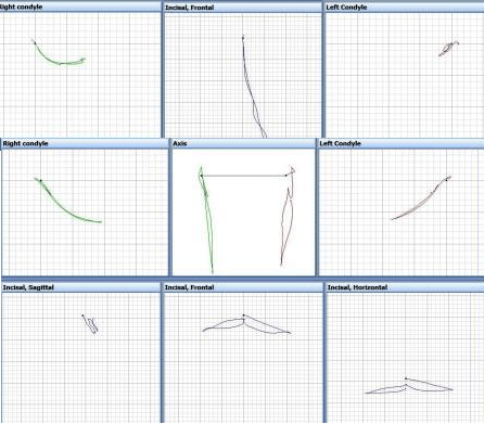
Figure 12. Trajectories of movements of the jaw: opening-closing and lateral movement.
Obtaining different trajectories in the same patient during multiple examinations over time.
First, the axiograph is attached to the patient's head, the trajectory is recorded (for example, opening and closing the mouth), and then the trajectories are displayed on the screen (Figure 13).
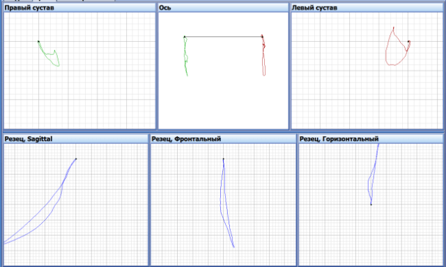
Figure 13. Trajectories of opening and closing the mouth.
Subsequently, the axiograph is completely removed from the patient's head and the same examination is conducted after 15 minutes. However, different trajectories were obtained in the next examination (figure 14).
Which data from these studies are correct?
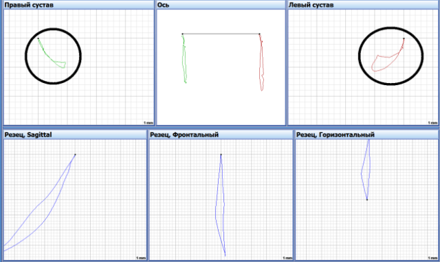
Figure 14. Trajectories recorded after 15 min. Opening-closing of the mouth.
Registration of lower jaw movements was also conducted, taking into account dental guides to obtain digital values of angles, and different data were obtained (figure 15).
Which data should be used to program the articulator?
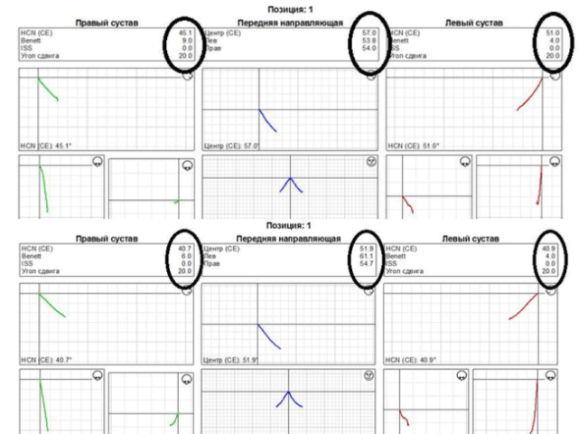
Figure 15. Various data for programming the articulator.
Errors primarily occur due to differences in the fixation of the ultrasonic axiograph on the patient's head during the aforementioned measurements. To partially solve these problems, it is necessary to preserve the registration obtained from the fork on the dental arch and not to change the position of the paraocclusal fork during studies with time intervals.
Solutions to Problems Arising in Electronic Axiography
The main result of our research was the creation of a more accurate and accessible device for recording mandibular movements and the adjustment of the electronic axiography method itself (fig. 16). We developed the Dentograf device (Prosystom).
Figure 16. Optical device for recording the articulation of n/ch Dentograf (Prosystom).
Today, Dentogaf is the most compact and easy-to-use device for tracking trajectories. It is an optical device that uses only one camera in its operation.
Considering the above-mentioned problems associated with attaching the sensor to the n/ch, we have designed special markers that allow for research under almost any pathology of the dental rows. Now, a deep incisal overlap is no longer an obstacle for research (figure 17).
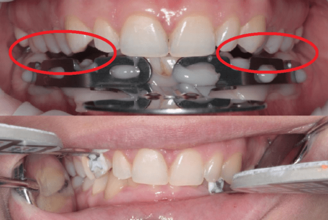
Figure 17. Arrangement of the paraocclusal fork and lateral markers of the Dentograf device.
One central sensor, which is used to determine the individual position of the prosthetic plane, two lateral ones (figure 18). One lateral marker is attached to the upper tooth, the other to the lower tooth. In this technique, we completely abandoned the use of median-anatomical face bows, thereby significantly increasing the accuracy of diagnostics.
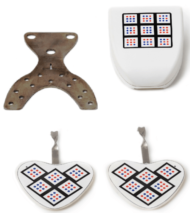
Figure 18. Dentograf device sensor set.
It has become possible to conduct studies without any problems in patients undergoing orthodontic treatment with the use of bracket systems (figure 19).
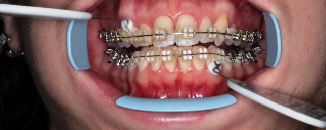
Figure 19. Placement of side sensors in patients with a bracket system on the teeth.
All the above-described techniques and equipment of Prosystom company allow for precise diagnostics and treatment planning in real space.
Stage III: Using a virtual articulator in primary functional diagnostics (working with virtual models)
The next important task that we tried to solve is the use of our capabilities in virtual space, namely working with virtual models.
What's new with the advent of virtual articulators?
A mechanical articulator can reproduce 3 trajectories: protrusion, right and left laterotrusion.
A virtual articulator can reproduce 3 trajectories: protrusion, right and left laterotrusion.
Virtual articulators are a complete analogue of mechanical ones, only the space has changed – from real to virtual.
How necessary are the existing virtual articulators if their functional capabilities are limited?
For example, why is it not possible to reproduce any trajectories in virtual space and what prevents this?
This is hindered by the virtual articulators available in today's software, or more precisely, their structure (figure 20).
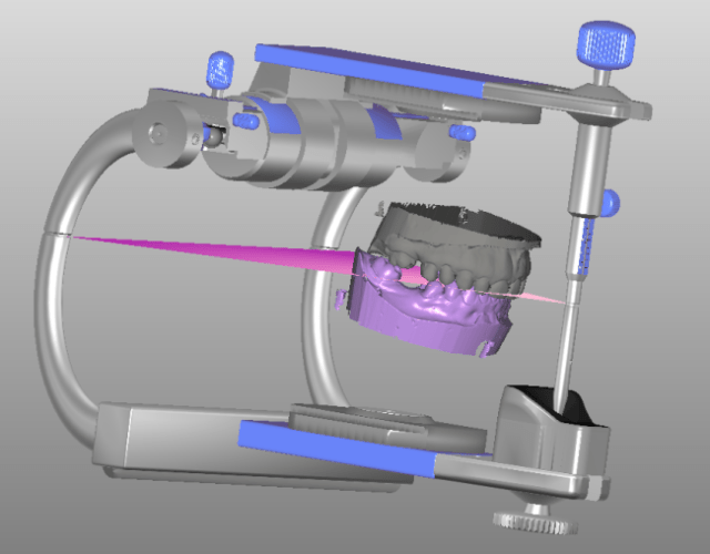
Figure 20. Virtual articulator.
Solving problems arising from the use of virtual articulators.
To work in virtual space, taking into account the individual parameters of the patient, the following are necessary: computed tomography, virtual models, motion trajectories, and correct orientation of the virtual model in/around and up/down.
If one tries to eliminate the articulator when working in virtual space, new promising opportunities arise:
- Individual alignment of virtual models and joints n/a. For this, it is necessary to use the patient's head CT and virtual models. Combining CT and models does not present major difficulties today (figure 21).
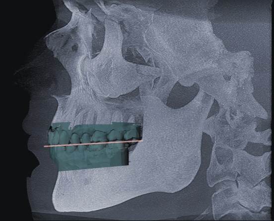
Figure 21. Integration of CT and virtual models.
- Reproduction of any articulation trajectories n/a using virtual models (figure 22). For this, we use the Dentograf device.
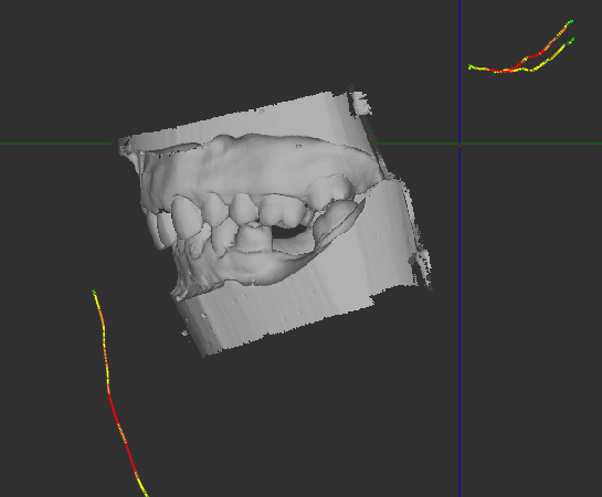
Figure 22. Trajectories of movement of particles and virtual models.
- Orientation of models in virtual space. The use of a central marker allows positioning the model of the particle in virtual space in the same way as in the patient (figure 23).
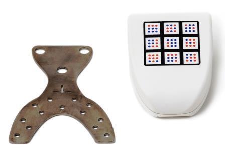
Figure 23. The use of a central marker for positioning models in virtual space.
Conducting Functional Diagnostics of CNS (Conclusion)
We have developed a comprehensive methodology and new equipment for conducting primary functional diagnostics of CNS. This equipment is universal for use in both real and virtual spaces with minimal errors.
Learn more about CNS lesion diagnostics in the webinar Radiological Examination of CNS. Advanced Level.
http://stomanet.ru/