
Influence of shaft design on the shaping ability of 3 nickel-titanium rotary systems by means of spiral computerized tomography
Objective. To evaluate the influence of shaft design on the shaping ability of 3 rotary nickel-titanium (NiTi) systems.
Study design. Sixty curved mesial canals of mandibular molars were used. Specimens were scanned by spiral tomography before and after canal preparation using ProTaper, ProFile, and ProSystem GT rotary instruments. One-millimeter-thick slices were scanned from the apical end point to the pulp chamber. The cross-sectional images from the slices taken earlier and after canal preparation at the apical, coronal, and midroot levels were compared.
Results. The mean working time was 137.22 ± 5.15 s. Mean transportation, mean centering ratio, and percentage of area increase were 0.022 ± 0.131 mm, 0.21 ± 0.11, and 76.90 ± 42.27%, respectively, with no statistical differences (P> .05).
Conclusions. All instruments were able to shape curved mesial canals in mandibular molars to size 30 without significant errors. The differences in shaft designs seemed not to affect their shaping capabilities. (Oral Surg Oral Med Oral Pathol Oral Radiol Endod 2008;105:807-13)
Root canal preparation is an important part of endodontic treatment. This procedure involves the use of instruments and substances to clean, shape, and disinfect the canals.
Recent advances in endodontic instrument design have made proper canal shaping more efficient and predictable. The most noteworthy advance was the development of nickel-titanium (NiTi) rotary instruments. In the present study, the tested rotary systems have dissimilar shaft designs, although they are produced by the same company (Dentsply Maillefer, Ballaigues, Switzerland). ProTaper shows a convex triangular cross-sectional design with a flute design that combines multiple tapers within the shaft. The ProFile system is a 3-fluted instrument of constant taper, with 3 radial lands, and a U-shaped cross-section. ProSystem GT rotary instruments feature a U-shaped blade design, a noncutting tip, and a variably pitch flute pattern.
A recently introduced nondestructive method to evaluate changes of root canal geometry after endodontic preparation is the high-resolution computerized tomography (CT) that allows 3-dimensional evaluation of root canal geometry before and after preparation, yielding a mass of exact metric data. Spiral computerized tomography (SCT) is a major advance in X-ray CT for rapid volumetric scanning and has been clinically accepted. The SCT has the primary advantage of scanning a complete anatomic volume in a single breath hold, ensuring slice-to-slice contiguity, and has been recommended when requiring high longitudinal resolution. Conversely, the resolution of micro-CT is definitely higher than SCT, but the former is time consuming and costly and cannot be used for human imaging in vivo.
The aim of the present study was to evaluate the influence of the shaft design on the shaping ability of ProTaper, ProFile, and ProSystem GT rotary NiTi systems in curved human root canals by means of SCT.
Materials and Methods
Pretest sample size calculations
In a one-way analysis of variance (ANOVA) study, sample sizes of 20, 20, and 20 are obtained from the 3 groups whose means are to be compared. The total sample of 60 subjects achieves 80% power to detect differences among the means, using an F test with a .05 significance level, considering 0.04 as the size of the variation in the means, and assuming the hypothesis of a common standard deviation of 0.10 (PASS, Power Analysis and Sample Size System, Kaysville, Utah).
Specimen selection, preparation, and scanning
Sixty canals of 30 mesial roots of extracted human mandibular molars were used. All roots were selected on the basis of mature apices, a severe canal curvature, and 2 distinct, separated canals. The crowns were sectioned slightly above the cementoenamel junction and the apical portions of the distal roots at 2 mm from the apex by a rotating diamond disc.
Access cavities were prepared and each canal negotiated with a 10K file. The working length (WL) was established by visualizing the file tip under ×40 magnification at the apical foramen minus 1 mm. With files in the canals, radiographs of the mesial roots were taken in the mesiodistal and buccolingual directions to confirm the presence of 2 distinct and separated canals. The teeth were placed in sodium hypochlorite solution (2.5%) for 30 min and stored in 0.5% aqueous chloramine solution. The degree and radius of curvature were determined using the methods described by Schneider and Pruett et al., respectively. To be included, the mesial canals had to have an angle of curvature greater than 20° and a radius of curvature smaller than 10 mm. The apical portions of the mesial roots were inserted into a 3-mm-thick wax baseplate and positioned in 6 columns of 5 teeth each. The wax baseplate was placed in an aluminum mold (100 × 80 × 6 mm) and embedded by freshly mixed clear polymer resin at the level of the furcation area. After polymerization, the acrylic plate with the teeth was removed from the metal mold and placed in an SCT unit (PQ5000; Picker, New York, NY) with the long axis of the roots perpendicular to the beam. Computerized tomography was carried out in spiral mode using 1.0 mm slice thickness and reconstruction interval of 0.5 mm. The field of view (FOV) was reduced to 60 mm, resulting in a pixel size of 0.1 × 0.1 mm using a matrix resolution of 512 × 512 pixels. The obtained sections (topograms) from each tooth, in DICOM format, were recorded onto digital recordable disks. Afterward, to recover from dehydration, the specimens were replaced into a 0.5% aqueous chloramine solution for 24 h.
Canal preparation
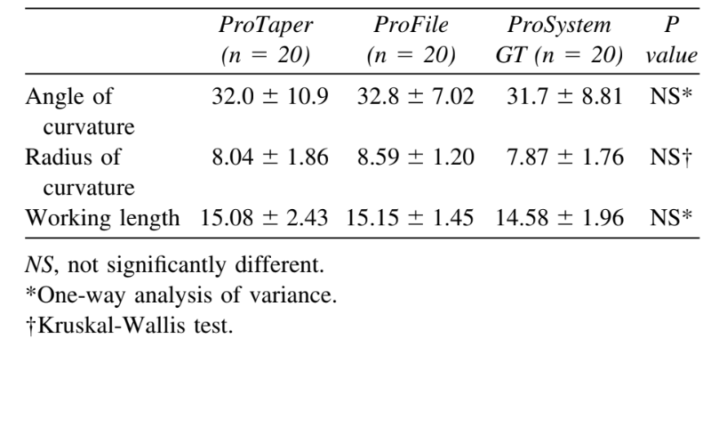
The 60 canals were randomly assigned into 3 experimental groups according to the rotary system used and stratified in such a manner that the averages of the root canal length and degree and radius of curvature of the groups were as close to each other as possible (Table I). The control group was used to compare the precision and accuracy of specimen positioning during initial and final scans and consisted of noninstrumented distal roots.
The mesial canals were initially preflared with a 15K file, to the WL and a Gates-Glidden bur #2 (Dentsply Maillefer) to 6 mm from the coronal opening. The step-back flaring of the remaining canal was performed using increasingly larger Gates-Glidden burs, from #3 to #4 at 2-mm steps shorter of each other.
Group 1 (n = 20). The ProTaper instruments were used at a rotary speed of 300 rpm. The S1 instrument was taken into the canal just short of the depth at which the hand file was taken previously. Then, the SX shaping instrument was used to move the coronal aspect of the canal away from the furcation danger zone and to improve radicular access. This was followed by using S1 and S2 instruments to WL. Shaping instruments were used with a brushing action on the withdrawal stroke to create straight-line access. Canal finishing was performed with F1, F2, and F3 to the WL, using a no-brushing motion and maximum care to reach the WL only once and for no more than 1 s.
Group 2 (n = 20). The ProFile instruments were used at a rotary speed of 250 rpm, in a crown-down manner, using picking motion. Orifice Shapers sizes 3 and 2 were used sequentially to flare the coronal and middle thirds. Instruments were then used in the following sequence: 25/06, 20/06, and 25/04, introducing two-thirds to three-quarters down the canal using light apical pressure. Each instrument was withdrawn when resistance was felt and followed by the next instrument size. For apical preparation, ProFile 20/04, 25/04, and 30/04 were sequentially used at the WL and was considered to be complete when instrument 30/04 passed to the WL without force. When an instrument failed to go to WL, the previous one was used again.
Group 3 (n = 20). The ProSystem GT instruments were used at a rotary speed of 350 rpm, in a crown-down manner, using picking motion. Instruments 35.12 and 50.12 were sequentially used to flare the coronal third. Then, instruments were used in the following sequence: 30/10, 30/08, 30/06, and 30/04, introducing two-thirds to three-quarters down the canal using light apical pressure. Each instrument was withdrawn when resistance was felt and followed by the next instrument size. Final shaping to the WL was achieved with a 30/04 instrument.
To avoid instrument separation, 5 canals were instrumented with 1 set of instruments using a 1:64 reduction electric rotary handpiece with torque control (EndoMate TC, NSK, Tokyo, Japan). The canals were irrigated with 5 mL of a 1% NaOCl between each instrument and kept flooded during instrumentation. In addition, to achieve a certain degree of uniformity and reduce interoperator variables, all experimental procedures were conducted by the same operator. Instrumentation time for each root canal, excluding the time needed for changing instruments and irrigation, was recorded. After root canal preparation, the teeth were scanned by means of an SCT, applying the initial scan parameter settings, and the data were stored for later use.
Image analysis
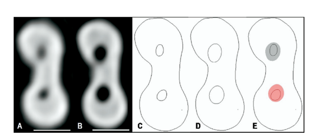
A total of 3 horizontal cross-sectional cut planes from each root, acquired during post- and preinstrumentation scans, were used for comparison. The first 2 cut planes were 3 mm from the apical end of the root (apical level) and 3 mm below the orifice (coronal level). A further cut plane (midroot level) was recorded dividing the distance between the first 2 cut planes into 2 equal lengths. The horizontal cross-sections in DICOM format, obtained from the CT scans, were imported into Adobe Photoshop CS (Adobe Systems, San Jose, CA) using the plug-in DICOM Access 1.5 (DesAcc, Chicago, IL; Fig. 1, A and B), and the canal outlines at each level were traced for better contrast (Fig. 1, C and D). The postoperative images were overlaid with 50% opacity on the preoperative images at the same position for comparison (Fig. 1, E). Only areas that could reasonably be expected to be reached by instruments were traced. Narrow communications between canals were excluded. The superimposed images were exported to Image Tool 3.0 software for image storage, measurement, and analysis. A standard scale measuring 5 mm was added at each image and used to calibrate the software.
Shaping assessment
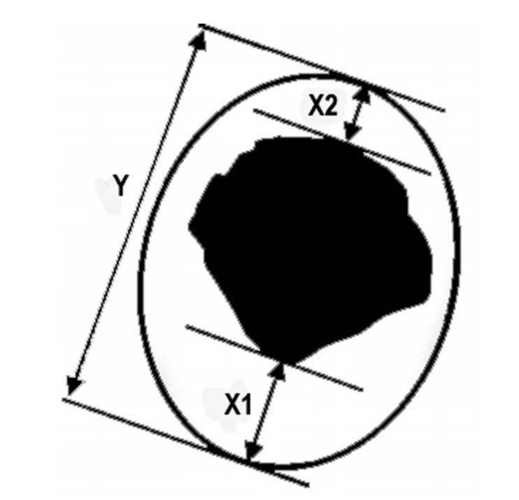
The mean centering ratio was calculated for each section by the formula [X1 — X2Y], where X1 represents the maximum extent of canal movement in one direction, X2 is the movement in the opposite direction, and Y is the diameter of the final canal preparation (Fig. 2). According to this formula, the centering ratio approaches zero as X1and X2 become closer. Zero is an indication of perfect canal centering and no canal transportation. The extent of canal transportation (X1) was determined by measuring the greatest distance between the periphery of the postinstrumented canal and the corresponding periphery of the preinstrumented canal that was overlaid on it. The direction in which X1, X2, and Y were measured was also noted. The percentage of area increase was calculated using the following formula: [100 — (A2 × 100)/A1], where A1 represents the area of the noninstrumented canal and A2 the area of the instrumented canal, in mm2.
Control group
The control group consisted of the noninstrumented distal root of each specimen. All values for all sections were measured by 2 evaluators and averaged. Intraobserver reproducibility was evaluated by the repeated measurement of 10 topograms randomly selected in an interval of 30 days. To determine whether initial and final scans were at the same level and inclination, data points that should not have changed from one scan to the next were compared.
Statistical analysis
To evaluate the instrumentation time for each system, statistical analysis was performed using Kruskal–Wallis test. One-way ANOVA and Tukey post hoc tests were used to compare the transportation and percentage of area increase before and after instrumentation. Paired t test was used to analyze control measurements and Pearson correlation analysis to estimate the relationship between the degree of curvature, transport, and percentage of area increase at the apical level. All statistical analyses were performed using SPSS software version 13.0 (Lead Technologies, Chicago, IL).
Results
Working time
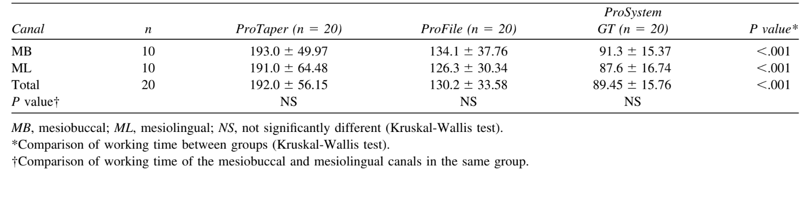
The mean time taken for preparation in the ProSystem GT group (89.45 ± 15.76 s) was considerably shorter than in the ProFile (130.2 ± 33.58 s) and ProTaper (192.0 ± 56.15 s) groups (Kruskal-Wallis, P< .001; Table II).
Centering ratio
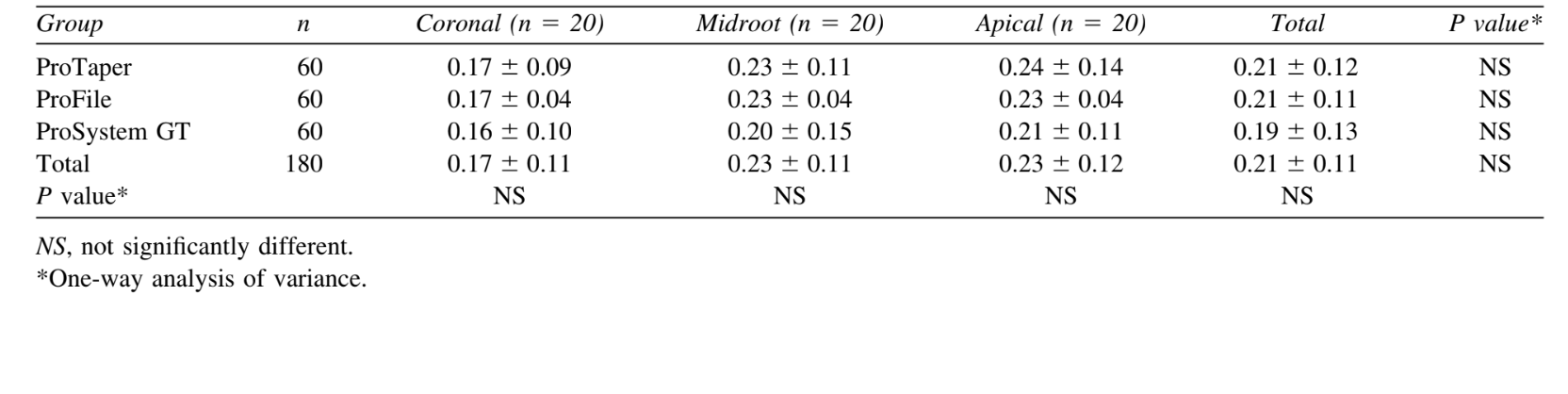
The mean centering ratio was 0.21 ± 0.12, 0.21 ± 0.11, and 0.19 ± 0.13 in the ProTaper, ProFile, and ProSystem GT groups, respectively, with no statistical differences (ANOVA: P> .05; Table III).
Canal transportation
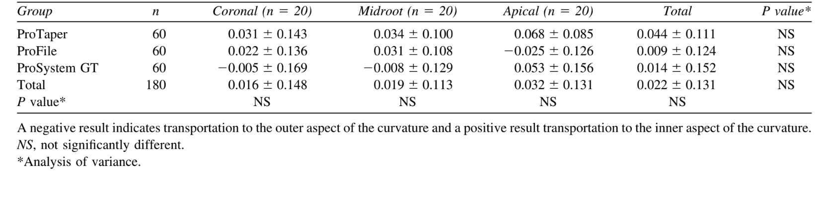
The mean transportation was 0.044 ± 0.111 mm, 0.009 ± 0.124 mm, and 0.014 ± 0.152 mm in the ProTaper, ProFile, and ProSystem GT groups, respectively, with no statistical differences (ANOVA: P> .05; Table IV). In general, transportation was toward the outer aspect of the curvature (n = 103). However, in all groups, transportation toward the inner aspect of the curve was also observed (n = 72).
Percentage of area increase
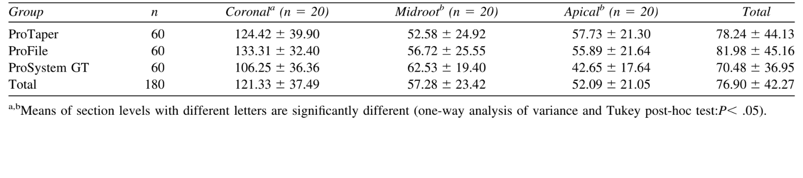
The mean percentage of area increase was 78.24 ± 44.13%, 81.98 ± 45.16%, and 70.48 ± 36.95%, in the ProTaper, ProFile, and ProSystem GT groups, respectively, with no statistical differences (ANOVA: P> .05; Table IV). Nevertheless, the mean percentage area increase at the cervical level showed significantly higher values than the midroot and apical levels (Tukey post hoc test: P< .05).
Correlation analysis
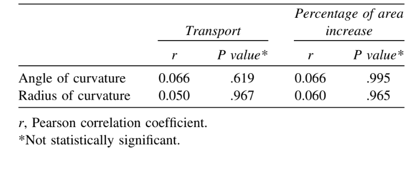
Considering the apical level of all experimental groups, there were no statistically significant relationship between degree of curvature, transport, and percentage of area increase (Pearson correlation analysis: P> .05; Table V).
Control specimens
Ten topograms were selected at random and remeasured by the same examiner in an interval of 30 days. The paired t test showed no significant difference between the 2 sets of measurements (P> .05). In determining whether initial and final scans were at the same level and inclination, no significant difference was found between the first and second scans when the X and Y values were compared (paired t-test: P> .05).
Discussion
In the present study, great care was taken to ensure comparability of specimens, because it could influence the results, thereby reducing the required amount of samples. This similarity is important, because earlier investigators advocated that studies comparing the effects of root canal instrumentation on canal anatomy should also consider details of preoperative geometry. To this end, roots that generally pose clinical problems, namely mesial roots of mandibular molars, were used. Although a high degree of similarity between groups was confirmed, the variety of root canal anatomy within the groups (Table I) still produced relatively high dispersion of the data.
The introduction of computer-based technology has led to important progress in 3D-demonstration of the canal system. Views in different planes of choice are possible as well as all kinds of rotations; however, the preparation irretrievably destroyed the examined samples. In SCT, a series of 2-dimensional image data sets can be integrated mathematically to produce cross-sections in any plane, with precision, without destroying the specimen. In addition, the SCT has been poorly investigated as a research tool in Endodontics.
Due to methodologic dissimilarities, as well as individual factors, earlier reports showed working time ranging from 34 to 346 s with ProTaper, 50 to 402 s with ProFile, and 50 to 389 s with ProSystem GT. Overall, NiTi system using only a small number of instruments completed preparation clearly faster than systems using a large number of instruments (Table II). In the present study, even with a small number of instruments compared with ProFile, the ProTaper group presented greater working time, probably owing to its multiple tapers within the shaft which result in more recapitulations and, as a result, more time needed.
Numerous studies evaluated shaping capabilities of instruments describing good or excellent maintenance of curvature even in severely curved root canals, owing to the combination of the crown-down instrumentation technique and some design characteristics, such as flexibility, flute design, and noncutting tip. On the whole, the total amount of canal transportation varied significantly in relation to canal geometry, ranging from 0.01 to 0.15 mm. In the present study, although produced by the same company, all of the tested instruments had dissimilar designs. The transportation and centering ratio had comparable scores in the coronal, middle, and apical portions of the canals, with no statistical differences (Tables III and IV). Furthermore, the transportation occurred toward both sides of the curve in all evaluated thirds, indicating that most areas of the root canal were touched.
The present results cannot be directly compared to the small number of earlier reports on the evaluation of root canal transportation using SCT, owing to differences in the methodologic approach. Overall, the findings achieved in the present investigation confirm those reports, demonstrating the ability of rotary NiTi instrument to stay centered in the canal with minimal transportation risk. The results have also shown that the ability of the instrument to stay centered in root canal may not entirely rest upon the U-file design or presence of generous radial lands. The highest results of transportation achieved for the ProTaper group (Table IV), although no statistical differences could be observed, may be due to the absence of radial land areas in combination with the large diameter of its shaft. Thus, a simpler convex triangular design, as exhibited by ProTaper instruments, was capable of performing equally to the more complex U-file design of ProFile and ProSystem GT. Furthermore, despite variations in instrument design and root canal anatomy of teeth, the Pearson correlation analysis indicated no statistically significant relationship between the degree of curvature and transportation in all experimental groups at apical level (Table V).
Although the method applied in this study did not provide reliable data regarding the amount of root dentin removal, the rationale behind measurement of changes in the cross-sectional area was to enable comparisons at standardized cut planes. Therefore, comparison with earlier works, which measured changes in the total area of the root canal system, is difficult. As previously demonstrated, superimposition of the cross-sections of the pre- and postoperative root canals has shown that all systems left uninstrumented canal walls in many cases. The present results have also demonstrated that, regardless of the rotary system used, the cross-sectional area increased at all levels. The difference was statistically significant only for the coronal third of the root canals (Table VI), owing to the cervical preflaring with Gates-Glidden burs, which has been suggested as an important step to improve working safety, avoiding apical transportation in curved canals, and reducing working time. Nevertheless, there was no difference between any rotary systems at any cut plane.
The majority of studies provide a strong consensus that larger apical preparation size not only allows proper irrigation but also produces a greater reduction in the remaining bacteria and dentinal debris compared with smaller apical preparation sizes. In the present study, the reason that the maximum apical preparation was size 30 was the fact that it was the largest diameter of the ProTaper system available.
The NiTi rotary instruments currently available vary considerably in their designs. The present study has confirmed earlier reports demonstrating the ability of rotary NiTi instruments to stay centered in the canal with minimal risk of transportation. Regardless of the unknown significance of the demonstrated amount of transportation, the clinical implication is probably minimal.
Conclusions
All instruments were able to shape curved mesial canals in mandibular molars to size 30 without significant errors. The differences in the shaft design seemed not to affect their shaping capabilities.
The authors are indebted to Mr. Ely Calhau Nery and Mr. William A. Moura for their contribution to CT evaluation and laboratory procedures, respectively.
Authors: Marco Aurélio Versiani, Elizeu Álvaro Pascon, Cássio José Alves de Sousa, Marco Aurélio Gagliardi Borges, Manoel Damião Sousa-Neto
References:
- Siqueira JF Jr. Reaction of periradicular tissues to root canal treatment: benefits and drawbacks. Endod Topics 2005;10: 123-47.
- Peters OA. Current challenges and concepts in the preparation of root canal systems: a review. J Endod 2004;30:559-67.
- Hülsmann M, Peters OA, Dummer PMH. Mechanical preparation of root canals: shaping goals, techniques and means. Endod Topics 2005;10:30-76.
- Bergmans L, Van Cleynenbreugel J, Beullens M, Wevers M, Van Meerbeek B, Lambrechts P. Smooth flexible versus active tapered shaft design using NiTi rotary instruments. Int Endod J 2002;35:820-8.
- Paqué F, Musch U, Hülsmann M. Comparison of root canal preparation using RaCe and ProTaper rotary Ni-Ti instruments. Int Endod J 2005;38:8-16.
- Al-Sudani D, Al-Shahrani S. A comparison of the canal centering ability of ProFile, K3, and RaCe nickel titanium rotary systems. J Endod 2006;32:1198-201.
- Veltri M, Mollo A, Pini PP, Ghelli LF, Balleri P. In vitro comparison of shaping abilities of ProTaper and GT rotary files. J Endod 2004;30:163-6.
- Gluskin AH, Brown DC, Buchanan LS. A reconstructed computerized tomographic comparison of Ni-Ti rotary GT files versus traditional instruments in canals shaped by novice operators. Int Endod J 2001;34:476-84.
- Rhodes JS, Pitt Ford TR, Lynch JA, Liepins PJ, Curtis RV. A comparison of two nickel-titanium instrumentation techniques in teeth using microcomputed tomography. Int Endod J 2000; 33:279-85.
- Kalender WA, Polacin A. Physical performance characteristics of spiral CT scanning. Med Phys 1991;18:910-5.
- Hübscher W, Barbakow F, Peters OA. Root-canal preparation with FlexMaster: canal shapes analysed by microcomputed tomography. Int Endod J 2003;36:740-7.
- Peters OA, Peters CI, Schönenberger K, Barbakow F. ProTaper rotary root canal preparation: effects of canal anatomy on final shape analysed by micro CT. Int Endod J 2003;36:86-92.
- Bergmans L, Van Cleynenbreugel J, Wevers M, Lambrechts P. A methodology for quantitative evaluation of root canal instrumentation using microcomputed tomography. Int Endod J 2001; 34:390-8.
- Uyanik MO, Cehreli ZC, Mocan BO, Dagli FT. Comparative evaluation of three nickel-titanium instrumentation systems in human teeth using computed tomography. J Endod 2006; 32:668-71.
- Tasdemir T, Aydemir H, Inan U,Unal O. Canal preparation with Hero 642 rotary Ni-Ti instruments compared with stainless steel hand K-file assessed using computed tomography. Int Endod J2005;38:402-8.
- Peters OA, Schönenberger K, Laib A. Effects of four Ni-Ti preparation techniques on root canal geometry assessed by micro computed tomography. Int Endod J 2001;34:221-30.
- Schneider SW. A comparison of canal preparations in straight and curved root canals. Oral Surg Oral Med Oral Pathol Oral Radiol Endod 1971;32:271-5.
- Pruett JP, Clement DJ, Carnes DL Jr. Cyclic fatigue testing of nickel-titanium endodontic instruments. J Endod 1997;23:77-85.
- Calhoun G, Montgomery S. The effects of four instrumentation techniques on root canal shape. J Endod 1988;14:273-7.
- Iqbal MK, Firic S, Tulcan J, Karabucak B, Kim S. Comparison of apical transportation between ProFile and ProTaper NiTi rotary instruments. Int Endod J 2004;37:359-64.
- Guelzow A, Stamm O, Martus P, Kielbassa AM. Comparative study of six rotary nickel-titanium systems and hand instrumentation for root canal preparation. Int Endod J 2005;38:743-52.
- Yang GB, Zhou XD, Zheng YL, Zhang H, Shu Y, Wu HK. Shaping ability of progressive versus constant taper instruments in curved root canals of extracted teeth. Int Endod J 2007; 40:707-14.
- Hartmann MSM, Barletta FB, Fontanella VRC, Vanni JR. Canal transportation after root canal instrumentation: a comparative study with computed tomography. J Endod 2007;33:962-5.
- Kum KY, Spångberg L, Cha BY, Il-Young J, Msd, Seung-Jong L, Chan-Young L. Shaping ability of three ProFile rotary instrumentation techniques in simulated resin root canals. J Endod 2000;26:719-23.
- Yun HH, Kim SK. A comparison of the shaping abilities of 4 nickel-titanium rotary instruments in simulated root canals. Oral Surg Oral Med Oral Pathol Oral Radiol Endod 2003;95:228-33.
- Schäfer E, Vlassis M. Comparative investigation of two rotary nickel-titanium instruments: ProTaper versus RaCe. Part 1. Shaping ability in simulated curved canals. Int Endod J 2004; 37:229-38.
- Bergmans L, Van Cleynenbreugel J, Beullens M, Wevers M, Van Meerbeek B, Lambrechts P. Progressive versus constant tapered shaft design using NiTi rotary instruments. Int Endod J 2003;36:288-95.
- Schaeffer MA, White RR, Walton RE. Determining the optimal obturation length: a meta-analysis of literature. J Endod 2005; 31:271-4.